Shaft sealing apparatus

a sealing apparatus and shaft technology, applied in the direction of engine fuction, engine seals, machines/engines, etc., can solve the problems of large-scale apparatus, increased manufacturing costs, and drastic changes in the pressure of purge gas as a sealing fluid for dry gas seals (i, non-contact mechanical seals)

Inactive Publication Date: 2001-10-23
NIPPON PILLAR PACKING CO LTD
View PDF84 Cites 7 Cited by
  • Summary
  • Abstract
  • Description
  • Claims
  • Application Information

AI Technical Summary

Problems solved by technology

However, the above-mentioned conventional shaft sealing apparatuses have had the following various problems.
That is, where the above-mentioned reservoir L is used, the entire apparatus becomes large-sized or the manufacturing cost increases.
Further, since the gas in the purge fluid area flows into the reservoir L without any resistance, where a high-pressure sealing fluid leaks from the mechanical seal, the pressure of the purge gas as a sealing fluid for a dry gas seal (i.e., non-contact type mechanical seal) drastically changes in such a manner that it rises up immediately and then drops at once failing to enable a stable dry gas sealing operation to be carried out.
Moreover, where the purge gas discharge line is directly coupled to the flare, since harmful gases from other various facilities of the plant gather in the flare, there is a danger of the harmful gases concentrated into the fl

Method used


Image

  • Shaft sealing apparatus
  • Shaft sealing apparatus
  • Shaft sealing apparatus

Examples


Embodiment Construction

The preferred embodiment of the present invention will now be described with reference to the accompanying drawings.

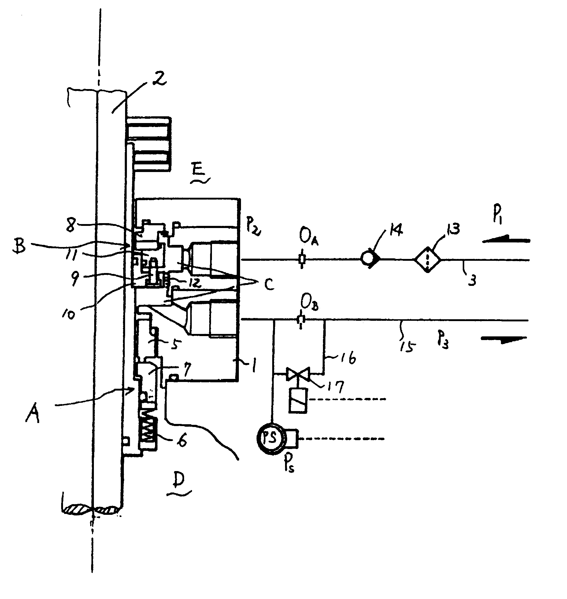
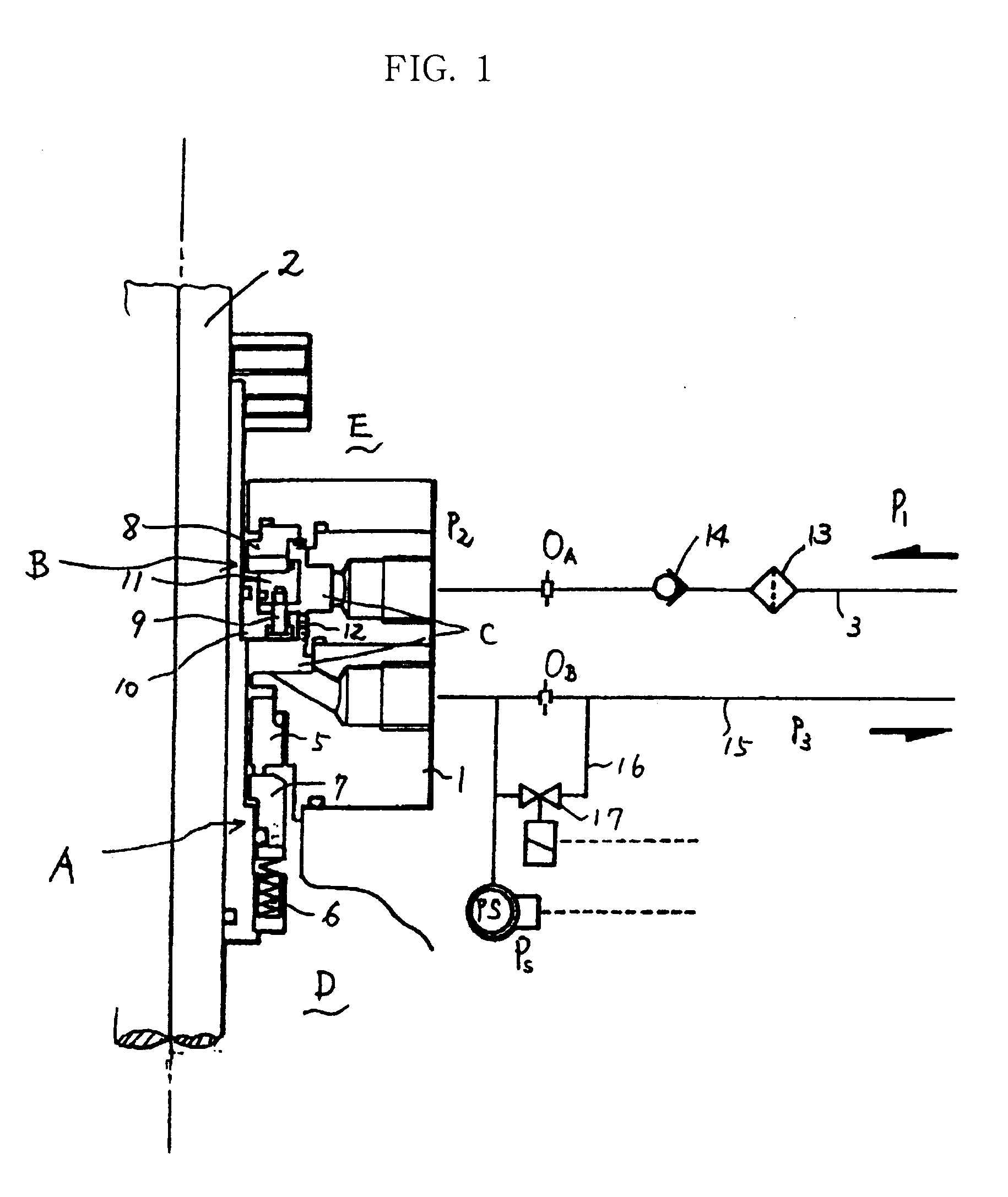
FIG. 1 is a system diagram of a shaft sealing apparatus according to one embodiment of the present invention wherein reference numeral 1 designates a seal casing and reference numeral 2 designates a rotary shaft passing through the seal casing 1. Further, as shown in FIG. 1 , a contact type mechanical seal A and a dry gas seal (i.e., non-contact type mechanical seal) B are mounted on the rotary shaft 2 in line with each other with the mechanical seal A located on the side of a target sealing fluid area D and the dry gas seal B located on the side of an atmospheric area E.

The mechanical seal A fixedly holds a stationary sealing ring 5 on the seal casing 1 and at the same time, allows a rotary sealing ring 7 to be biased by sping bias force 6 toward the stationary sealing ring 5 to be slidably held on the rotary shaft 2 in the axial direction.

Further, the dry gas seal B ...


PUM


Abstract

A shaft sealing apparatus capable of preventing gases vaporized from a gas seal or purge fluid from leaking outside before a pressure switch operates due to a pressure rise resulting from a fluid leakage from a mechanical seal. The apparatus comprises a seal casing and a rotary shaft passing through the former and having a mechanical seal A and a dry gas seal B mounted thereon in line with each other to provide purge fluid areas C therebetween. With this arrangement, a purge fluid is supplied to one of the purge fluid areas through a supply line having an orifice OA and the supplied purge fluid and a leaked part of a target fluid to be sealed are released outside from the other purge fluid area through a relief line having an orifice OB. The relief line is provided with a bypass line with an electromagnetic valve and a pressure switch and bypassing the orifice OB. In this case, the purge fluid supply pressure P1, the preset pressure P2 between the orifices OA and OB, the pressure P3 in the area from the orifice OB to outside and the pressure switch operating pressure P<SMALLCAPS>s </SMALLCAPS>satisfy the relationships of P1>P<SMALLCAPS>s</SMALLCAPS>>P2>P3.

Description

1. Field of the InventionThe present invention relates to a shaft sealing apparatus for various kinds of pumps handling various low boiling point inflammable fluids such as butane, methane, ethane, propane, LNG (Liquefied Natural Gas) and etc.2. Prior ArtConventionally, in the case of pumps handling low boiling point and highly inflammable fluids such as butane, methane, ethane, propane, LNG and etc., it has been usual that a reservoir L is used so as to store and supply or pressure-supply a buffer solution or a sealing solution used for the mechanical seal M of a shaft sealing apparatus whereby a fluid leaking from the contact type seal is released outside (for example, into the flare) instead of being introduced into the atmosphere.Further, there has been used a shaft sealing apparatus as described in Japanese Unexamined Patent Publication H6-42650 which has a favorable and stabilized sealing function in a high-pressure condition or with respect to a volatile or low boiling point ...

Claims


Application Information

Patent Timeline
IPC IPC(8): F16J15/34F16J15/16F16J15/40
CPCF16J15/3404F05D2260/6022
Inventor FUSE, TOSHIHIKO
Owner NIPPON PILLAR PACKING CO LTD
Why Eureka
Try Eureka