Control method for induction motor

a technology of inverter and control method, which is applied in the direction of motor/generator/converter stopper, dynamo-electric converter control, dynamo-electric gear control, etc., can solve the problems of inconvenient operation, adversely affecting the ride, inverter apparatus, etc., and achieve the effect of short tim

a technology of inverter and control method, which is applied in the direction of motor/generator/converter stopper, dynamo-electric converter control, dynamo-electric gear control, etc., can solve the problems of inconvenient operation, adversely affecting the ride, inverter apparatus, etc., and achieve the effect of short tim

US9065368B2Active Publication Date: 2015-06-23HITACHI LTD

Image

  • Control method for induction motor
  • Control method for induction motor
  • Control method for induction motor

Examples


Embodiment Construction

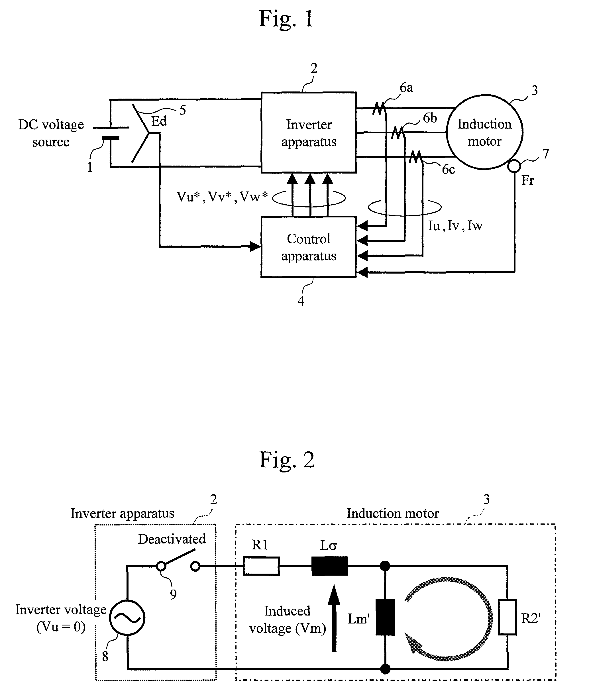
[0028]FIG. 1 illustrates a configuration of an induction motor drive apparatus according to an embodiment of the present invention. The drive apparatus according to the embodiment includes an inverter apparatus 2 and a control apparatus 4. The inverter apparatus 2 converts direct-current power obtained from a direct-current voltage source 1 into three-phase alternating-current power and supplies the three-phase alternating-current power to an induction motor 3. The induction motor 3 converts the three-phase alternating-current power obtained from the inverter apparatus 2 into axial torque.

[0029]The control apparatus 4 calculates alternating-current voltage commands Vu*, Vv*, and Vw* for the inverter apparatus 2 on the basis of: a voltage Ed of the direct-current voltage source 1 detected by a voltage detection unit 5; alternating-current currents Iu, Iv, and Iw detected by current detection units 6a, 6b, and 6c; and a rotation speed Fr of the induction motor 3 detected by a speed de...


PUM


Abstract

In order to cause the residual magnetic flux in an induction motor to decay in a short time without an excessive current flow, an induction motor control apparatus continues an operation in which an inverter apparatus is caused to output a zero voltage to the induction motor for a predetermined time before deactivating an operation of the inverter apparatus.

Description

BACKGROUND[0001]1. Technical Field[0002]The present disclosure relates generally to an apparatus for driving an induction motor.[0003]2. Related Art[0004]As a motor drive system for industrial applications, a system by which an induction motor or a synchronous motor is variable-speed driven by using an inverter apparatus is widely used. For example, in railway vehicles, generally one to four induction motors are driven by a single inverter apparatus.[0005]A railway vehicle typically accelerates from a deactivated state by starting the inverter apparatus, transitions to a coasting state in which the vehicle runs through inertia while the inverter apparatus is deactivated, and then accelerates or decelerates from the coasting state by restarting the inverter apparatus.[0006]In the coasting state, the inverter apparatus is deactivated, so that no voltage is applied from the inverter apparatus to the induction motor. In principle, however, the magnetic flux in the induction motor does n...

Claims


Application Information

Patent Timeline
23 Jun 2015
Publication
US9065368B2
IPC
H02P21/00; H02P3/18; H02P27/06; H02P21/22; H02P21/36; H02P23/07; H02P23/16; H02P27/08
CPC
H02P3/18; H02P27/06; H02M7/48; H02P21/00
Inventors
TACHIHARA, SHUICHI; KOJIMA, TETSUO