Transmission with integrated PTO input gear damper

a technology of pto input and gear damper, which is applied in the field of transmission, can solve the problems of excessive gear noise at the interface between the drive gear, noise generated by components, and noise typically occurring when the engine is operating at low revolutions per minute, so as to reduce the operation noise of pto, reduce noise, and absorb vibration

Active Publication Date: 2015-06-30
ZF FRIEDRICHSHAFEN AG
View PDF3 Cites 5 Cited by
  • Summary
  • Abstract
  • Description
  • Claims
  • Application Information

AI Technical Summary

Benefits of technology

[0007]The descriptions below include apparatuses and methods for reducing the operation noise of PTOs. A transmission may include a damper at a point along the torque path from the transmission PTO output gear to the PTO output. The damper absorbs vibrations and rattling in the PTO components and correspondingly may decrease the noise caused by the backlash of the gears or other components along the torque path.

Problems solved by technology

Typically, in engine-driven PTO applications, excessive gear noises are generated at the interface between the drive gear, which may be a gear in a transmission, and the PTO input gear due to backlash.
Components may generate noise due to their backlash, particularly when the components are unloaded.
Noise typically occurs when the engine is operating at low revolutions per minute (“RPM”) due to torsional vibrations from the engine that excites the gear mesh of the drive gear and PTO input gear.
Noise may also occur during PTO operation when the PTO is operating with a low torque load at the output side of PTO.
This noise results in decreased efficiency and may be irritable or harmful to the operator of the vehicle or equipment that is driven by the PTO.

Method used


Image

  • Transmission with integrated PTO input gear damper
  • Transmission with integrated PTO input gear damper
  • Transmission with integrated PTO input gear damper

Examples


Embodiment Construction

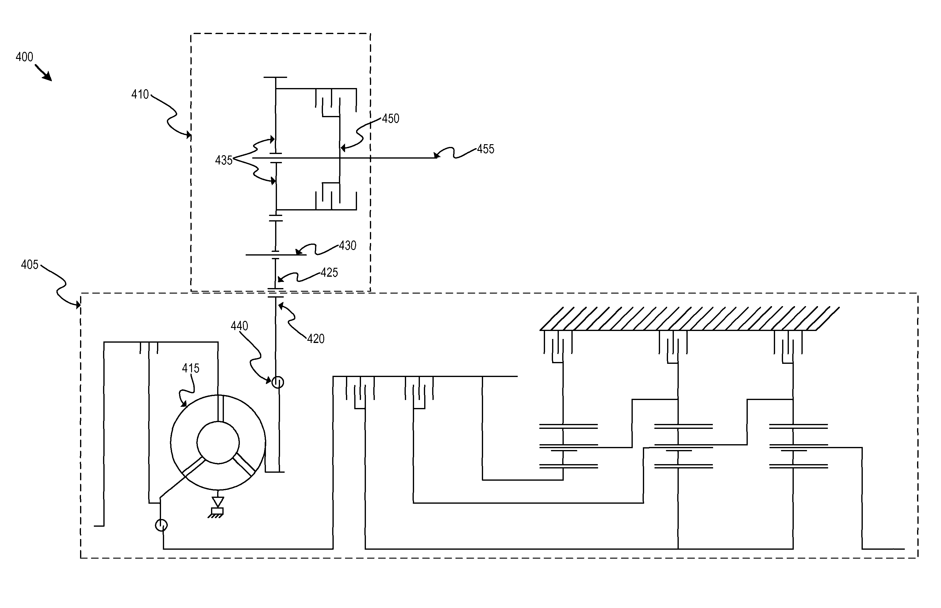
[0019]The described embodiments may alleviate the excessive noise generated when operating a PTO, particularly at low torque loads and / or at low RPMs. A vehicle transmission that integrates or interfaces with a PTO may include a damper to reduce noise generated by the transmission / PTO interface or in the PTO due to low RPM operation of the PTO, or due to backlash. Alternatively, the damper may be located in the PTO. The disclosed embodiments may be used with engine- or rear-driven PTOs.

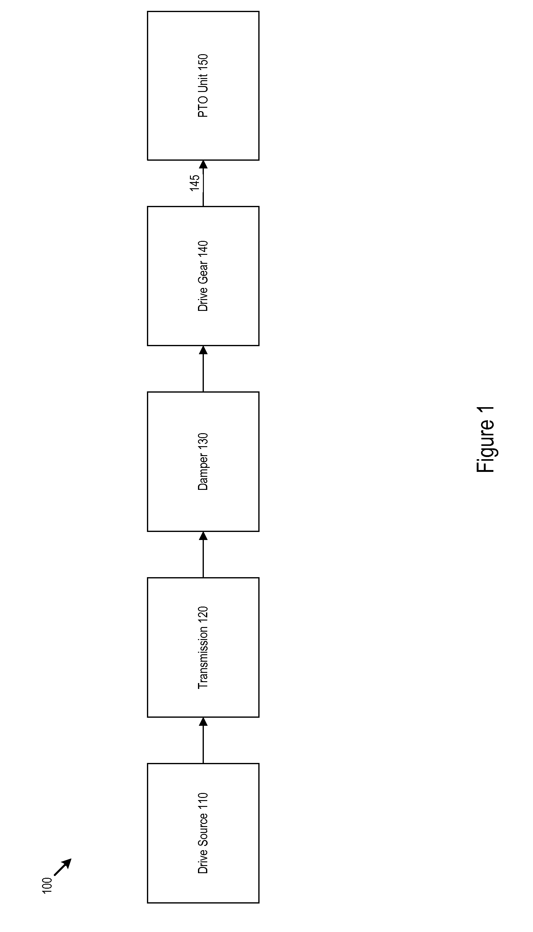
[0020]FIG. 1 illustrates a block diagram of damped system 100 according to one embodiment of the invention. Drive source 110 may be an engine, e.g., an internal combustion or diesel engine. Drive source 110 is coupled to transmission 120, which may be, for example, a manual or automotive transmission. Transmission 120 is coupled with damper 130, which may be a fluid damper, spring damper, or another type of damper.

[0021]Damper 130 may dampen the vibrations in damped system 100 by absorbing, for exampl...


PUM


Abstract

A power take-off unit (“PTO”) may include a damper to reduce noise while the PTO is operating at low torque or at low RPM. The damper may also be located in the transmission before the PTO driver gear. A method may be used to systematically measure the frequency and / or amplitude of the vibrations that cause noise and to adjust the damping constant of a damper to reduce the noise.

Description

BACKGROUND OF THE INVENTION[0001]1. Field of the Invention[0002]The invention relates to transmissions that use power-take off units (“PTOs”). In particular, the invention relates to transmissions that interface with a PTO using a PTO drive gear.[0003]2. Related Art[0004]PTOs provide a convenient means to power accessories or secondary functions of a vehicle or other powered equipment. PTOs may be used with vehicles of all types, including, but not limited to, automobiles, trucks, marine vessels, or airplanes. A PTO may also be used with an industrial engine. A PTO may interface directly with an engine, or may interface with a transmission that is used with an engine. Generally, the output of a PTO is a shaft to which other devices or equipment can be attached and powered. For example, the output of a PTO may be used to power a hydraulic pump, winch, or dump truck bed lift. PTOs may be driven by any torque carrying shaft in the engine, transmission, or vehicle.[0005]A common arrange...

Claims


Application Information

Patent Timeline
Patent Type & Authority Patents(United States)
IPC IPC(8): B60K17/28F16F15/12F02B67/04
CPCB60K17/28F16F15/12Y10T74/19623F02B67/04
Inventor HAIRSTON, BERRONWHITE, BRADFORD
Owner ZF FRIEDRICHSHAFEN AG
Why Eureka
Try Eureka