Treatment of produced hydrocarbon fluid containing water

a hydrocarbon fluid and produced technology, applied in the direction of fluid removal, pipeline systems, borehole/well accessories, etc., can solve the problems of large infrastructure and cost, system prone to recurring problems, and large space and weight, so as to reduce the water dew point, control the formation of hydrates, and limit the size of hydrate particles.

Active Publication Date: 2015-06-30
SINVENT AS
View PDF15 Cites 3 Cited by
  • Summary
  • Abstract
  • Description
  • Claims
  • Application Information

AI Technical Summary

Benefits of technology

[0008]The present invention provides a method and a system for treating a production flow of gas, hydrocarbon liquid and water from a hydrocarbon production field in a simple system and enabling further processing and / or transport of the desired products through a transportation system, including one or more pipelines.

Problems solved by technology

This requires large infrastructure and cost in order to inject and regenerate MEG.
A full gas drying, e.g. by a tri ethylene glycol (TEG) process, will here require significant space and weight.
Though in widespread use, such systems are plagued with a host of recurring problems—most of which can be traced back to poor efficiency of the first-stage separator for a well fluid.
That task is formidable, and results in high-cost equipment and high operating costs.
Though much focus is presently on gas fields and avoidance of their water problems, many of the same problems also appear in liquid-rich oil / condensate systems, where even small fractions of water in the total system may over time lead to significant problems or flow blockages.
Water and its solidification is thus a general problem for modern oil and gas production systems.

Method used


Image

  • Treatment of produced hydrocarbon fluid containing water
  • Treatment of produced hydrocarbon fluid containing water
  • Treatment of produced hydrocarbon fluid containing water

Examples


example 1

Gas Production from an Offshore Field with a Production Platform or Ship (or Onshore Gas Production in a Cold Region)

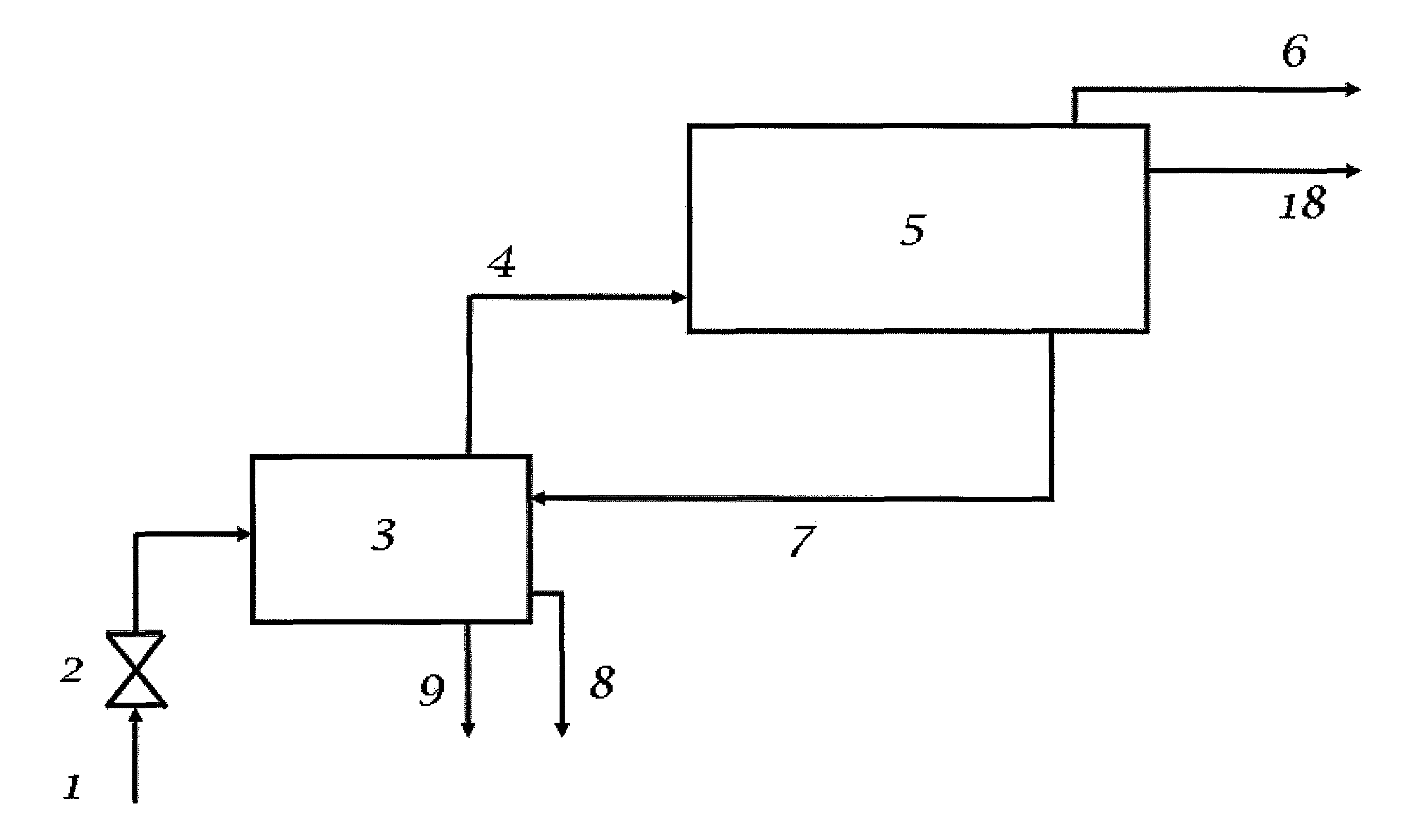
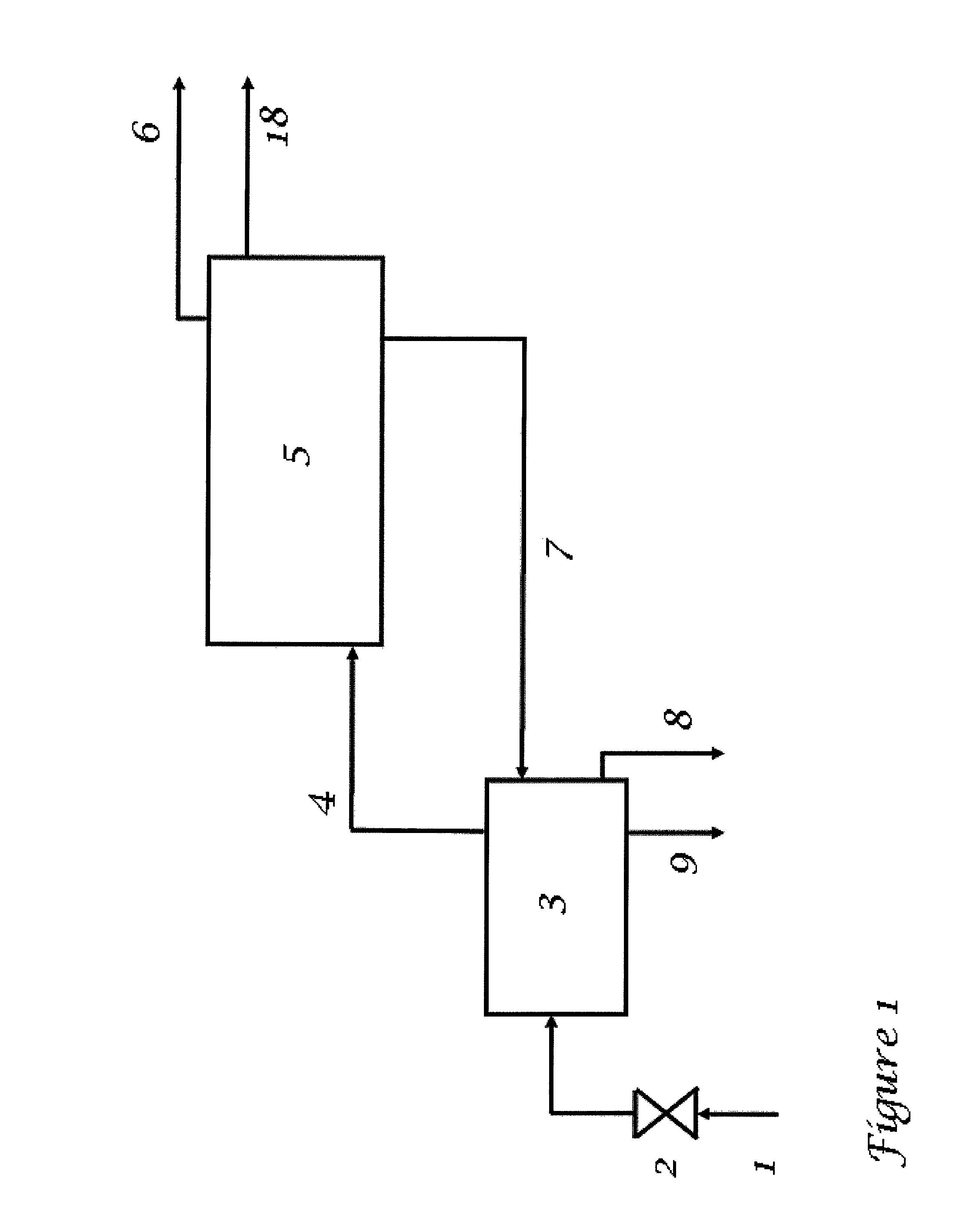
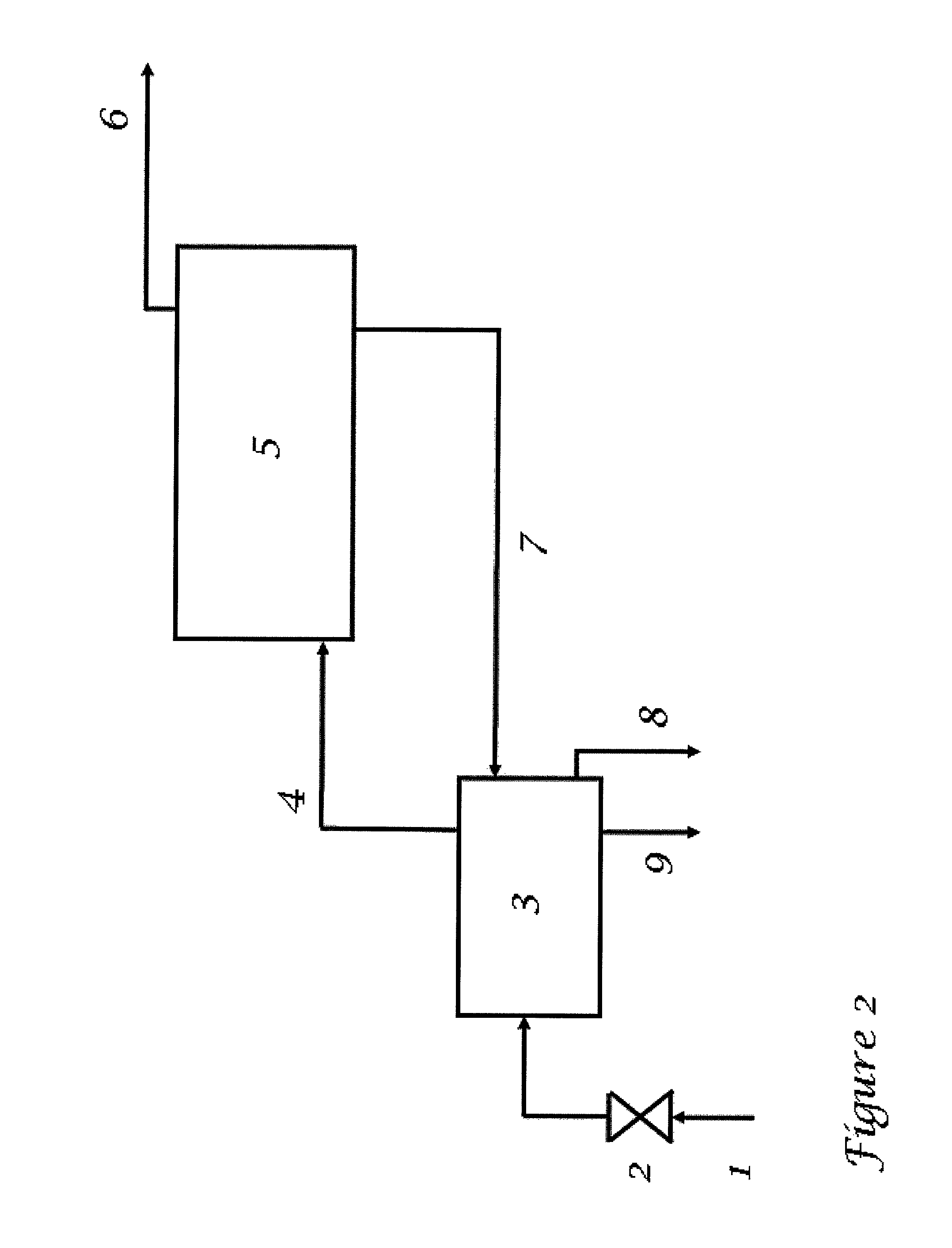
[0069]An implementation of the present invention might consist of the following steps:[0070]The gas production is choked down to a suitable pressure, if needed.[0071]The gas and any liquid first passes through a warm (usually above 20° C.) separator (which is also used to melt excess hydrate from later process steps).[0072]Gas (4) and condensate (8) from the warm separator (3) pass on to the mixing point (10)(FIG. 3), where they meet a cold (usually −2 to 8° C.) gas hydrate slurry (16) from a cold separator (15)[0073]The mixture is flowed through a pipeline (11) which utilizes heat exchange with cold outside water (or air) as a means of cooling.[0074]Whenever suitable, satellite wells may be connected to the flow (11) with shorter or longer tie-backs, or alternatively be lead into the warm separator (3) as extra production stream (directly from the satellite to the pl...

example 2

Gas Production from a Subsea Installation

[0083]For most purposes in this embodiment, the process flow will be the same as described in Example 1 above. The main difference is that all equipment is moved subsea, to a central location where production from the most gas-rich and formation water rich production wells are gathered, allowing enough heat to apply the melting step for excess hydrate slurry in the warm separator (3). The remaining production wells (less gas, less formation water) may be simply phased into cooling loop (11) through shorter or longer tie-backs.

example 3

Oil Production from a Subsea Installation, or a Platform, with Processing Possibilities Both Subsea and Topsides

[0084]An implementation of the present invention is in many respects identical to the preceding, and might include, but not limited to, the following steps:[0085]The production flow (1), containing oil, gas, water, and / or condensate, is choked (2) down to a suitable pressure, if needed.[0086]The fluid flow (1) first passes through a warm (usually above 20° C.) separator (3) (which is also used to melt excess hydrate from later process steps).[0087]Liquid hydrocarbon (8) and gas (4) (containing water vapour) from the warm separator (3) pass on to the mixing point (10) (FIG. 3), where they meet a cold (usually −2 to 8° C.) gas hydrate slurry (16) from a cold separator (15)[0088]The mixture is flowed through a pipeline (11) which utilizes heat exchange with cold outside water (or air) as a means of cooling.[0089]Whenever suitable, satellite wells may be connected to the flow ...


PUM


Abstract

A method for treating a flow of fluid hydrocarbons containing water includes introducing the flow of fluid hydrocarbons into a first separator and separating at least free water from said flow of fluid hydrocarbons, wherein a remainder of said fluid hydrocarbon flow is introduced into a system converting free / condensed water in the fluid hydrocarbon flow in said system to gas hydrates, and providing at least a first fluid flow and a second fluid flow, wherein said first fluid flow is a liquid phase including gas hydrates, said first fluid flow is recycled into the first separator, and wherein the second fluid flow has a content of dry gas and / or condensate / oil. A system for treatment of a flow of fluid hydrocarbon fluid containing water includes the following elements listed in the flow direction and connected with each other: connection to a hydrocarbon production source (1), a first separator (3) operative to separate at least free water from said fluid flow, a converting system (5) for converting free / condensed water to gas hydrate, a pipeline (6, 18) for transporting a dry gas or condensate / oil; and in addition a line (7′) which leads from the converting system (5) to the first separator (3) providing a first recycling flow including gas hydrates.

Description

[0001]This application claims the benefit of U.S. Provisional Application No. 61 / 312,790, filed Mar. 11, 2010.INTRODUCTION[0002]The invention concerns a system for treating a flow of fluid hydrocarbons containing water, and a method for such treatment.BACKGROUND[0003]Some of the world's largest gas fields are found offshore in deep water (e.g. Ormen Lange) or in remote areas in the arctic (e.g Snøhvit and Shtockman). The usual way today to transport such unprocessed well fluids in a pipeline to a landside terminal is by adding monoetylene glycol (MEG) at the wellheads. This requires large infrastructure and cost in order to inject and regenerate MEG.[0004]For very long pipelines (e.g. Shtockman), processing and drying (water) of the gas phase may be needed prior to subsea pipeline transportation, e.g. at a platform or a ship. A full gas drying, e.g. by a tri ethylene glycol (TEG) process, will here require significant space and weight.[0005]One common way to solve water problems and...

Claims


Application Information

Patent Timeline
Patent Type & Authority Patents(United States)
IPC IPC(8): E21B43/34F17D3/14
CPCE21B43/34F17D3/14
Inventor LUND, ARELARSEN, ROARKASPERSEN, JON HARALDSTRAUME, ERLEND ODDVINFOSSEN, MARTINHJARBO, KAI W.
Owner SINVENT AS
Why Eureka
Try Eureka