
Domestic water recycling apparatus and fluid contamination detection system therefor

a technology of fluid contamination detection and domestic water, which is applied in the direction of service pipe system, investigation of moving fluid/granular solids, treatment water, etc., can solve the problems of high water consumption, scarce clean water, and high water treatment costs, and achieve stable flow of used water, prevent turbulence, and proper filter efficiency

Active Publication Date: 2015-07-07
ORBITAL SYST
View PDF15 Cites 10 Cited by
  • Summary
  • Abstract
  • Description
  • Claims
  • Application Information

AI Technical Summary

Benefits of technology

[0006]It has been discovered that the combination of an optical detector that detects certain small sized (non-filtered) contaminants and a filter that removes large sized (filtered) contaminants can provide an efficient wastewater recycling system that overcomes drawbacks of prior art systems.
[0007]It is therefore an object of the present invention to provide a wastewater recycling system that optically detects specific (non-filtered) contaminants smaller than a predetermined filter pore size such that, when contaminants are not optically detected, water is filtered and recycled. Any contaminant larger that the filter pore size need not be optically detected whereas contaminants smaller than the filter pore are optically detected based on wavelength specific absorption / emission signatures.
[0008]It is another object of the present invention to provide an automatic recycling shower system that does not require user input other than temperature and flowrate which can, if desired, be manually selected by the user. In such a system, a directional device automatically directs water to either a recycling conduit or to an outflow conduit for discharge based on the presence of one or more non-filterable contaminants.
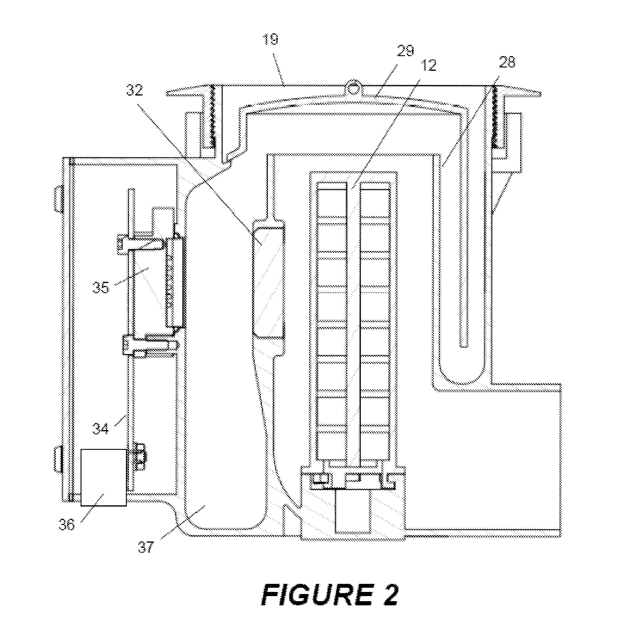
[0013]Based on the outputs from the detectors, the controller of the system operates directional apparatus for directing the water in the chamber to either the outflow conduit or the recycling conduit. The directional apparatus may include an electronically actuated valve or one or more pumps. The system may also use a filtration apparatus that traps particulate matter from fluid passing from the chamber to the recycling conduit. The filtration apparatus may be located in a chamber separate from the detection chamber in which the water is examined by the optical detection apparatus. In addition, a filter cleaning system may be used that passes a cleaning solution through the conduits of the system and which may be operated to dislodge particulate matter accumulated by the filtration apparatus and discard it via the outflow conduit. The filter cleaning system may use a flow of water that passes from the recycling conduit to the chamber. In one embodiment, the recycling shower uses a baffle that deflects used water as it enters the chamber region and inhibits turbulence in the used water accumulating in the chamber. This reduces the presence of bubbles in the used water that might otherwise affect the transmission of the optical signals through the used water, and helps maintains a constant, stable flow of used water through the detection reservoir. A disinfection unit, such as an ultraviolet lamp, may also be used with the system to kill bacteria in the uncontaminated water returned to the distribution point.
[0014]In some embodiments of the present invention, when non-filtered contaminants such as soap, blood and urine are not detected but the optical detection capability is impeded by a significant amount of particulate matter (filtered contaminants) such as dirt, sand and hair, water is automatically discharged to the drain, thus ensuring proper filter efficiency.
[0015]In accordance with the present invention, there is also provided an automated method for reducing energy and fresh water consumption while taking a shower comprising the steps of collecting shower water from a shower drain and detecting the presence of certain contaminants using the optical absorption characteristics of the contaminants. Following detection, shower water will be discharged if contaminants are detected or recycled if contaminants are not detected. When water is recycled, it first passes through a filter of appropriate pore size to remove unwanted particulate contaminants. Water temperature is also adjusted using a combination of recycled and fresh water, thus returning a combined temperature adjusted water to a shower head.

Problems solved by technology

In many parts of the world, clean water is becoming a scarce commodity.
Water treatment to remove contaminants can be effective, but is often costly, or uses technology that is not readily available.
One area of high water consumption is the household shower, in which water is continuously distributed from a showerhead and collected by a drain below.
Moreover, the types of contaminants that enter the water in the shower are typically limited, and enter sporadically.
While effective to a certain extent, these methods are inherently limited in their ability to control the recycling of shower water with a high degree of efficiency or with a high degree of confidence regarding a true level of contamination of the used water.
In recycling shower systems of the prior art, removing certain particulate contaminants from recycled water was found to be an important issue.
This system would, however, require a pump of significant power / energy input in order to force water through a filtering device of such small porosity and would not permit the removal of soluble contaminants.

Method used


Image

  • Domestic water recycling apparatus and fluid contamination detection system therefor
  • Domestic water recycling apparatus and fluid contamination detection system therefor
  • Domestic water recycling apparatus and fluid contamination detection system therefor

Examples


Embodiment Construction

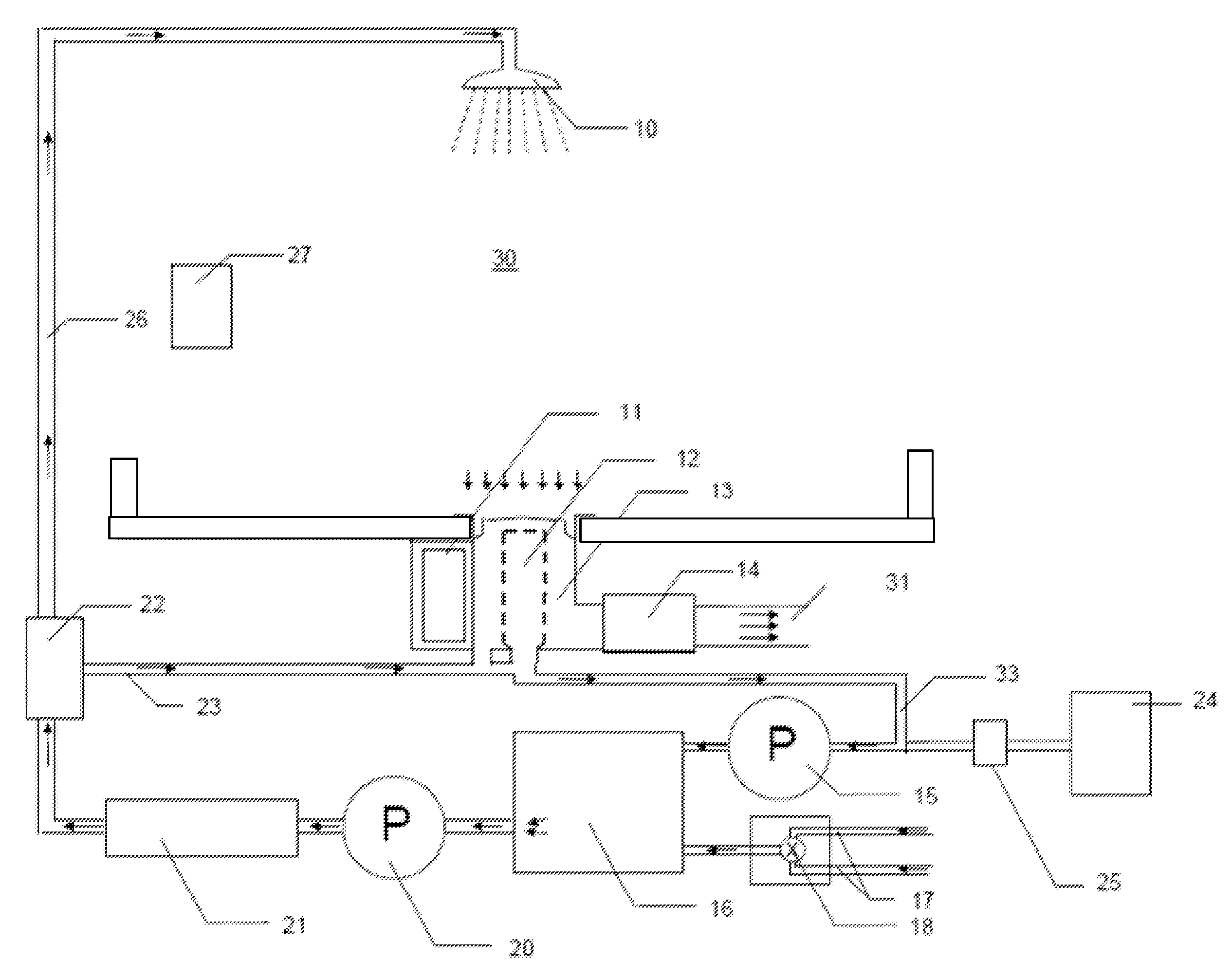
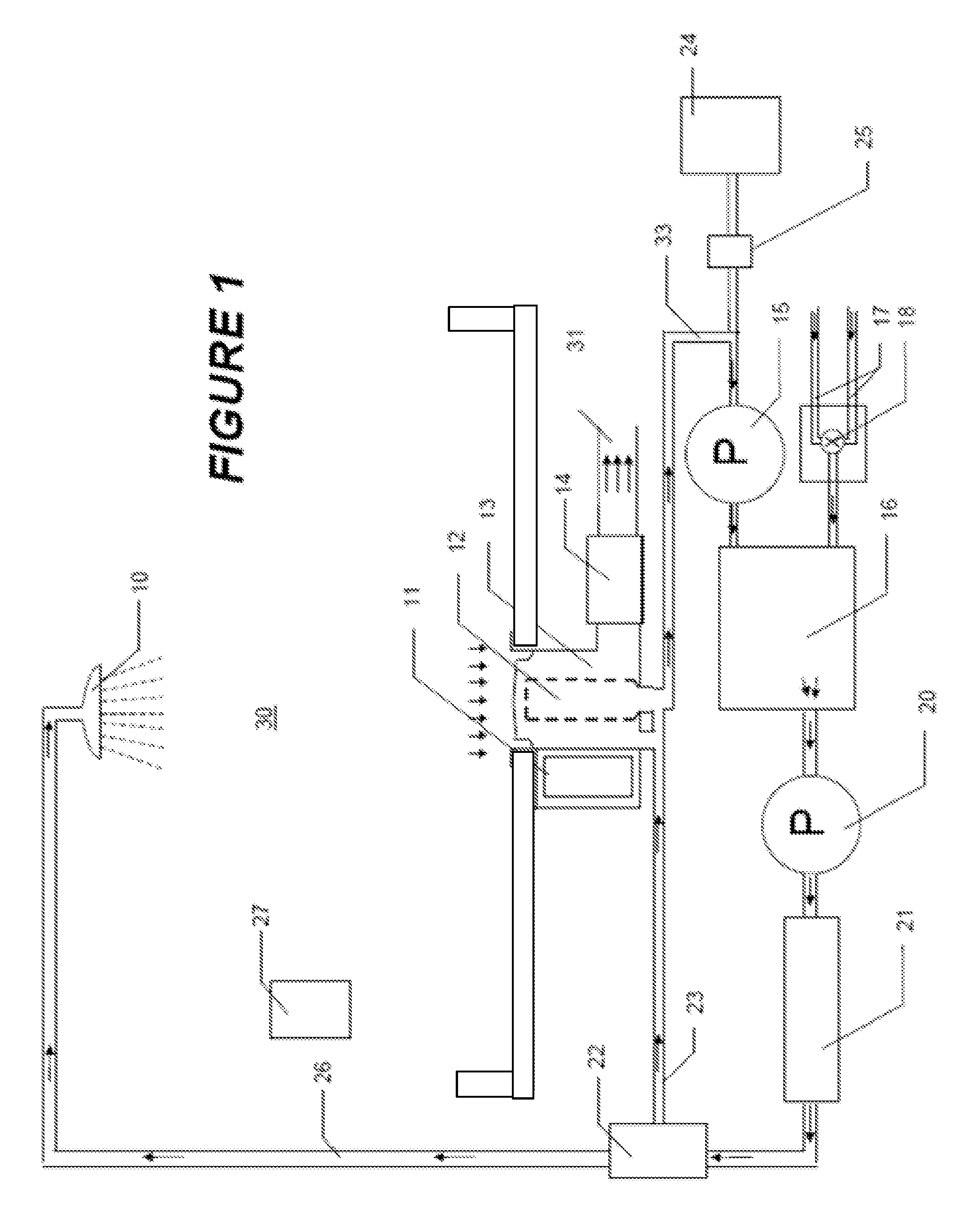
[0024]Shown in FIG. 1 is a water recycling shower unit according to the present invention. Water enters the shower system via hot and cold water supply pipes 17. The valve apparatus 18 controls the relative flow of hot and cold water, respectively, from the pipes 17 to a mixing chamber 16. Water is then drawn from the mixing chamber by pump 20, and directed past disinfection unit 21 and valve 22 to conduit 26. The water is thereafter directed via the conduit 26 to showerhead 10, which distributes it within a space 30 below, where a user may be located.

[0025]Water output via the showerhead eventually passes through a drain to a collection chamber 13, along with any contaminants that may be been accumulated within the shower space 30. Located in the collection chamber 13 is a filtration apparatus 12, and access to two possible outflow conduits for the water collected therein. A first is via wastewater pipe 31, and the other is via recycling pipe 33, which directs clean water back to m...


PUM

PropertyMeasurementUnit
pore sizeaaaaaaaaaa
pore sizesaaaaaaaaaa
characteristic wavelengthaaaaaaaaaa

Abstract

A domestic water recycling system using a combination of an optical detector to detect certain smaller sized (non-filtered) contaminants and a filter to remove larger sized (filtered) contaminants provides an efficient wastewater recycling system. Optical detection of contaminants determines whether water is discharged or filtered and recycled. The optical detection system can use several discrete optical wavelengths that are passed through the fluid, and can determine a relative presence of the contaminants based on the resulting wavelength response. A recycling shower using optical detection, an electronically actuated directional device and pump and a controller allows for automatic recycling or discharging of water without requiring user input. The system may include a turbulence reduction baffle in a collection chamber, and a disinfection unit for the recycled water.

Description

CROSS-REFERENCE[0001]This application is the US national stage of International Patent Application No. PCT / IB2009 / 052399 filed on Jun. 5, 2009, which claims priority to U.S. Provisional Patent Application No. 61 / 059,004 filed on Jun. 5, 2008.FIELD OF THE INVENTION[0002]This invention relates generally to the field of detection and removal of contaminants in fluids and, more specifically, to a domestic water recycling apparatus using such detection.BACKGROUND OF THE INVENTION[0003]The detection and removal of contaminants in a fluid finds application across many fields, including the field of water consumption and recycling. In many parts of the world, clean water is becoming a scarce commodity. Water treatment to remove contaminants can be effective, but is often costly, or uses technology that is not readily available. One area of high water consumption is the household shower, in which water is continuously distributed from a showerhead and collected by a drain below. The water in...

Claims


Application Information

Patent Timeline
Patent Type & Authority Patents(United States)
IPC IPC(8): C02F1/00E03B1/04C02F9/00G01N21/85E03B3/18A47K3/022E03C1/00C02F1/32C02F1/78G01N21/94C02F103/00
CPCE03B1/04C02F9/005G01N21/85E03C1/00C02F1/001C02F1/32C02F1/78C02F2103/002C02F2209/005C02F2209/02C02F2209/40E03B2001/045G01N21/94G01N2201/0627Y02A20/148G01N15/06G01N2015/0687G01N2015/0693Y10T137/794Y10T137/0318C02F9/20
Inventor JALLON, ROMAINBLAIS-OUELLETTE, SEBASTIENVALETTE, ANTOINE
Owner ORBITAL SYST
Learn More