Thus, although they have many advantages, concrete buildings have relatively poor energy efficiency.
While insulated concrete forms of the prior art provide relatively
high energy efficiency, they lack the strength to withstand the relatively high fluid concrete pressures experienced by conventional concrete forms.
Consequently, they are relegated mostly to residential construction or low-rise construction and find few applications in commercial construction.
However all types of foam have relatively low strength and structural properties.
Therefore, insulated concrete forms of the prior art are relatively weak and cannot withstand the same high pressures experienced by conventional forms.
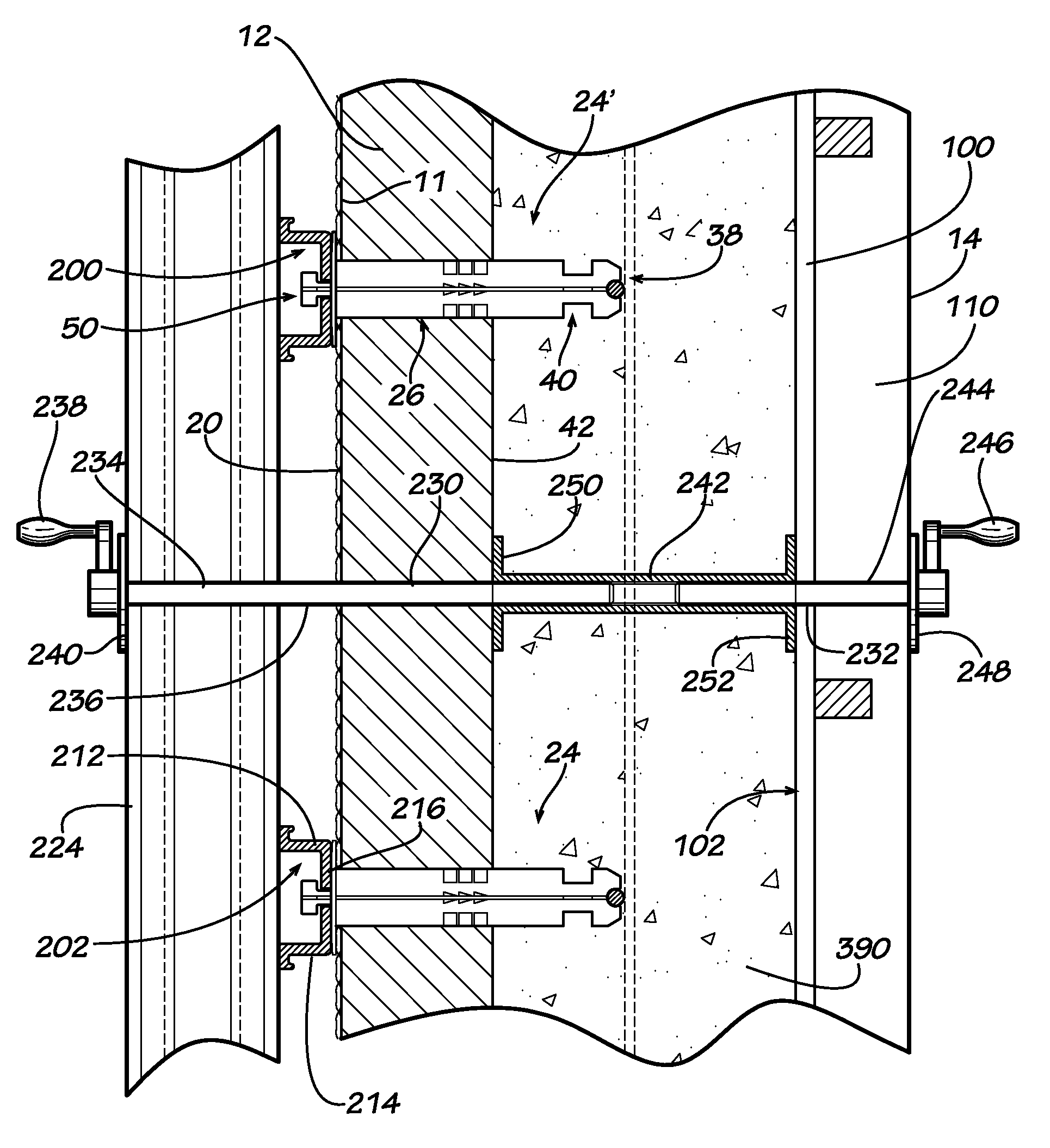
First, all insulated concrete forms are made of two opposing foam panels connected by a plurality of connecting ties. The concrete is placed between the foam panels in a plastic state. Once the concrete hardens the form stays in place whereby both foam panels are attached to the inside and outside face of the concrete wall, respectively. The ties anchor each layer of the foam panels into the concrete. In this configuration, the concrete
thermal mass is mostly if not completely encapsulated within the two foam panels. Therefore, the concrete wall has a foam panel attached to both the inside and outside face. In many cases it is not necessary to insulate both the inside and outside face of the wall. Since concrete has a high
thermal mass, it may be desirable in certain cases that the
thermal mass be exposed to the climate controlled inside of the building. In same cases, it may be desirable for the concrete wall to be exposed to the outside while the concrete face facing the inside of the building needs to be insulated. State of the art insulated concrete forms are not designed to have any of the foam panels removed, they are only designed to stay in place. If only one side of the concrete requires an insulating foam panel, it would be very difficult, expensive and
time consuming to remove the other foam panel from an insulated concrete form once the concrete has been cured. Conventional concrete forms are designed to be removed once the concrete has achieved a desired strength. However, conventional concrete forms do not provide insulation to the concrete wall, either during concrete curing or after removal.
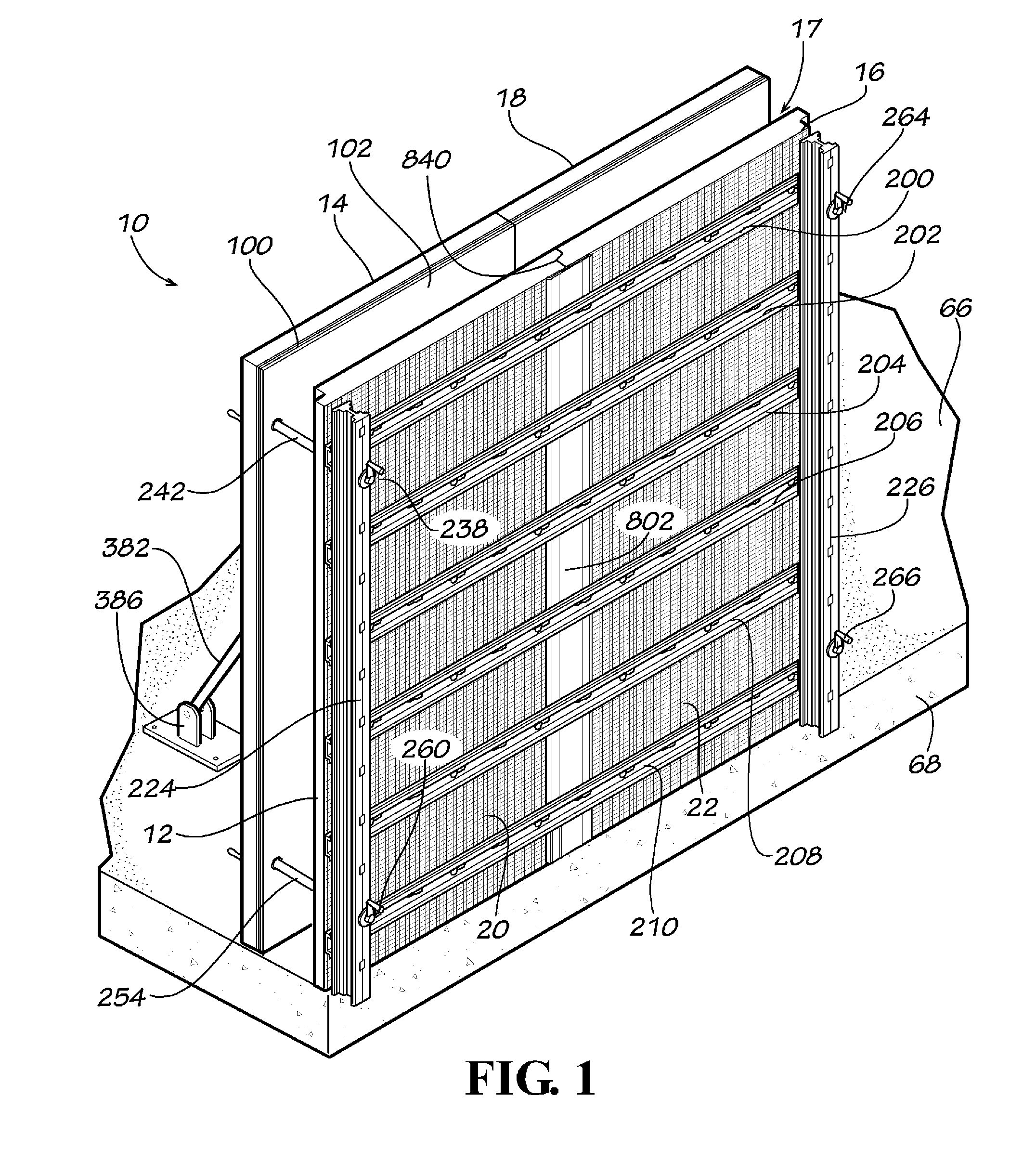
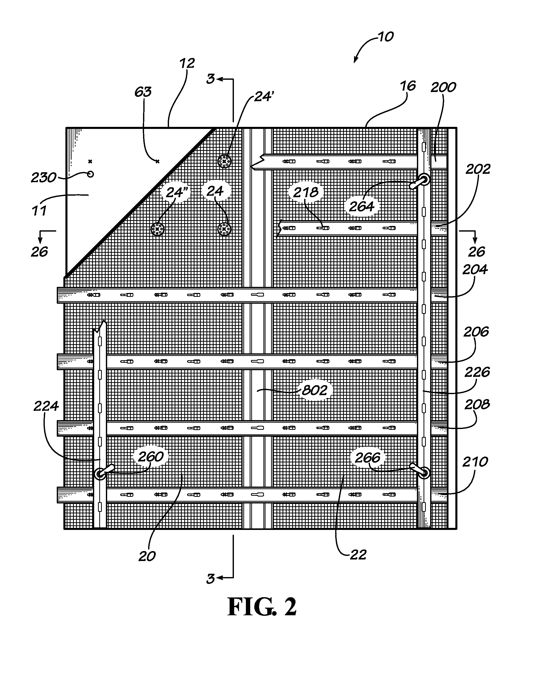
Second, in the construction of an exterior wall of a building, multiple insulated concrete form modules are stacked upon and / or placed adjacent to each other in order to construct a concrete form of a desired height, length and configuration. In some insulated concrete form systems, the form spacers / interconnectors are placed in the joints between adjacent concrete form modules. Such form systems are not strong enough to build a form more than a few feet high. Concrete is then placed in the form and allowed to harden sufficiently before another course of insulating forms are added on top of the existing forms. Such systems result in cold joints between the various concrete
layers necessary to form a floor-to-ceiling wall or a multi-story building. Cold joints in a concrete wall weaken the wall therefore requiring that the wall be thicker and / or use higher strength concrete than would otherwise be necessary with a wall that did not have cold joints. This generally limits current use of insulated concrete forms to buildings of a single story or two in height or to
infill wall applications.
Third, the use of multiple form modules to form a wall, or other building structure, creates numerous joints between adjacent concrete form modules; i.e., between both horizontally adjacent form modules and vertically adjacent form modules. The sum of all these joints makes the prior art insulated concrete forms inherently unstable and concrete blowouts are not uncommon. Since the wall forms are unstable, the use of additional forming materials, such as plywood, to stabilize the modular insulated concrete forms is required before concrete is poured. These additional materials are costly and
time consuming to install. The multiple joints also provide numerous opportunities for water to seep into and through the concrete wall. Furthermore, some of the prior art wall spacer systems create holes in the insulated concrete forms through which water can seep, either in or out. Thus, the prior art modular insulated concrete forms do little, or nothing, to prevent water intrusion in the finished concrete wall.
Fourth, prior art modular insulated concrete form systems are difficult and
time consuming to put together, particularly at a constructions site using unskilled labor.
Fifth, prior art modular insulated concrete form systems do little, or nothing, to produce a stronger concrete wall.
Sixth, prior art modular insulated concrete form systems do not meet the
high pressure ratings that conventional concrete forms do.
Seventh, prior art modular insulated concrete form systems are designed to form walls and are not suitable for forming columns or piers.
Eighth, prior art modular insulated concrete form systems do not allow for forming of structural,
load bearing high-rise construction
Ninth, prior art modular insulated concrete form systems only allow for one type of wall cladding to be applied, such as a directly applied finish
system.
To install all other wall claddings, additional systems have to be installed, sometimes at greater expense than even in the conventional concrete forming systems.
Some prior art modular insulated concrete form systems do not allow for the use of other types of wall cladding systems.

