Oscillator

a crystal unit and oscillator technology, applied in the field of crystal units, can solve problems such as bad quality of tuning fork crystal units

Inactive Publication Date: 2015-07-07
NIHON DEMPA KOGYO CO LTD
View PDF5 Cites 2 Cited by
  • Summary
  • Abstract
  • Description
  • Claims
  • Application Information

AI Technical Summary

Benefits of technology

[0006]The oscillator using such the tuning-fork resonator has the tuning-fork crystal unit on which the IC chip is bonded with an adhesive agent. Then, for connecting terminals of the IC chip (IC terminals) and output terminals (mounting terminals), a lead frame is used. After connecting the terminals using the lead frame, a resin-molding is performed to provide as a single electronic part. After the resin molding, the lead frame goes through a cut off process of unnecessary portion, and is folded on the back surface of the oscillator unit to be used as the mounting terminal.
[0009]Furthermore, if the lead frame is connected to the IC terminals of the IC chip with wires, and is fold to the IC mounting surface side to become the mounting terminal after the resin molding, the output frequency may varies after the mounting on the base plate of applying equipment. Specifically, the crystal terminals and an IC pad inside the oscillator come close to the base plate of the applying equipment, increasing the stray capacity. This may decreases the output frequency.

Problems solved by technology

If the adhesive agent flows over the crystal terminals, the film of the adhesive agent, which is an insulating material, disrupts the electrical connection with the IC chip terminals (IC terminals), resulting in one of the causes that render the tuning-fork type crystal unit a bad quality item.

Method used


Image

  • Oscillator
  • Oscillator
  • Oscillator

Examples


embodiment 1

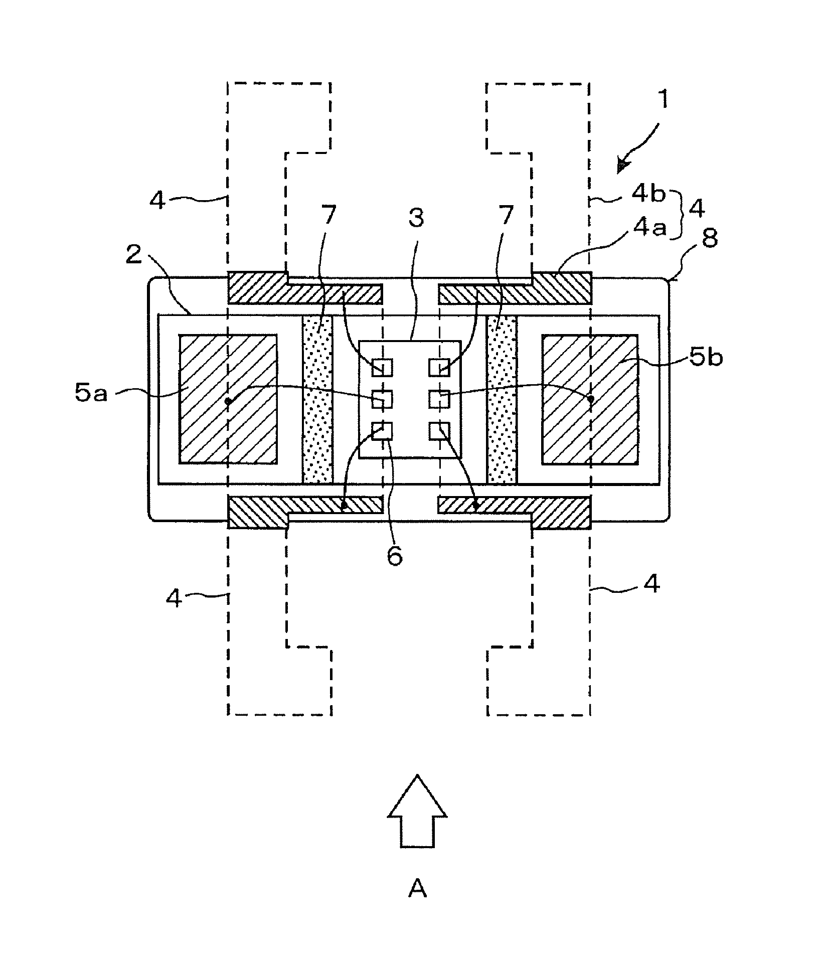
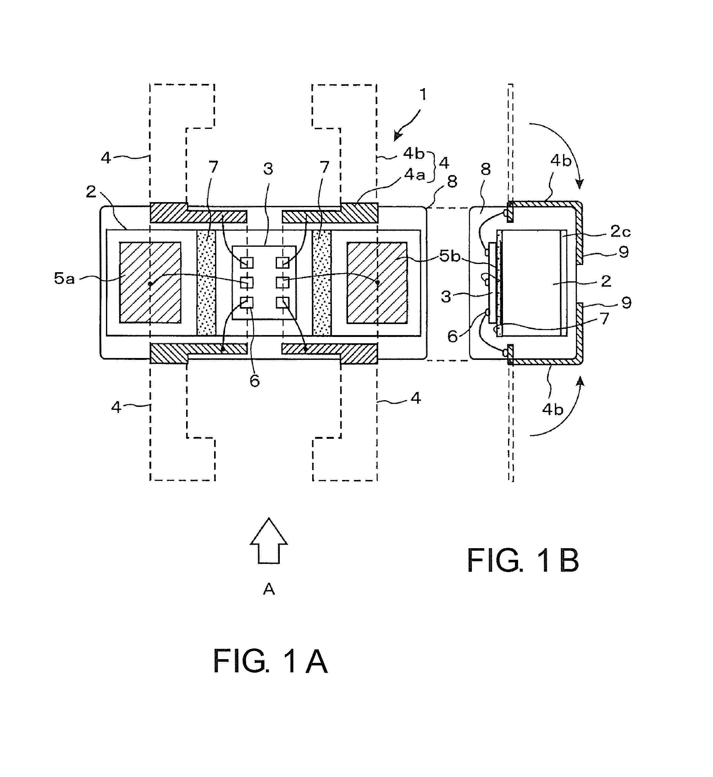
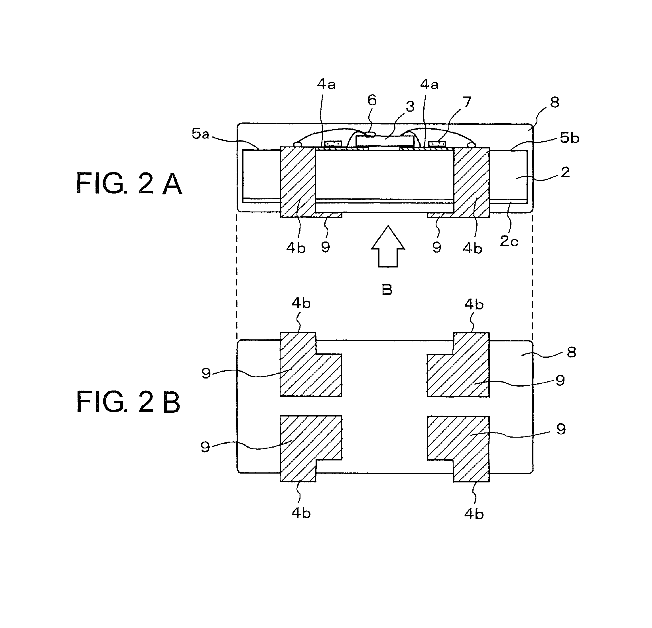
[0028]FIGS. 1A and 2B are explanatory drawings of Embodiment 1 of the oscillator according to this disclosure. FIG. 1A is a top view of the oscillator, and FIG. 1B is a side view in the short side of the oscillator. Similarly to FIG. 1A, FIG. 1B, FIG. 2A, and FIG. 2B is an explanatory drawing of Embodiment 1 of the oscillator according to this disclosure. FIG. 2A is a side view in the long side viewed from the direction of arrow “A” in FIG. 1A. FIG. 2B is a bottom view viewed from the direction of arrow “B” in FIG. 2A.

[0029]In FIG. 1A, FIG. 1B, FIG. 2A, and FIG. 2B, reference numeral “1” indicates the oscillator, reference numeral “2” does the tuning-fork crystal unit, and reference numeral “3” does the IC chip. The tuning-fork type crystal unit 2 includes a concave ceramic container internally housing the tuning-fork type resonator (the tuning-fork type crystal resonator). After housing the tuning-fork type resonator, the opening portion of the concave ceramic container is sealed w...

embodiment 2

[0037]FIGS. 3A and 3B are explanatory drawings of Embodiment 2 of the oscillator according to this disclosure. FIG. 3A is a top view of the oscillator, and FIG. 3B is a side view in the short side of the oscillator. Like FIG. 3A, FIG. 3B, FIGS. 4A, and 4B is explanatory drawings of Embodiment 2 of the oscillator according to this disclosure. FIG. 4A is a side view in the long side viewed from the direction of arrow “A” in FIG. 3A, and FIG. 4B is a bottom view of the oscillator viewed from the direction of arrow “B” in FIG. 4A.

[0038]In FIG. 3A, FIG. 3B, FIG. 4A and FIG. 4B, functional portions same as those in Embodiment 1 are designated as the same reference numerals. The difference in the oscillator between Embodiment 1 and Embodiment 2 is the configuration of the adhesive agent flow prevention film 7 disposed between the crystal terminals 5a, 5b and the IC chip 3. The other configurations are similar to those in Embodiment 1. Hence the explanation is omitted.

[0039]The adhesive age...

embodiment 3

[0043]FIGS. 5A and 5B illustrate a side view in the short side and a bottom view describing Embodiment 3 of the oscillator according to this disclosure. FIG. 5A is a side view in the short side of the oscillator in Embodiment 3, and FIG. 5B is a bottom view of the oscillator viewed from the direction of arrow “C” in FIG. 5A. The oscillator according to Embodiment 3 has the structure equal to the tuning-fork crystal unit in any of Embodiment 1 above-described in FIGS. 1A and 1B and Embodiment 2 above-described in FIGS. 3A and 3B.

[0044]The feature point of Embodiment 3 which is different from Embodiment 1 and Embodiment 2 is the structure of the mounting terminal. In Embodiment 1 and Embodiment 2, as illustrated in FIGS. 1A and 1B, for example, the structure in which, after the cut off process of the unnecessary portion of the lead frame 4, the mounting terminal forming portion 4b is folded parallel along the back surface of the tuning-fork type crystal unit 2 so as to join the mounti...


PUM


Abstract

An oscillator according to the disclosure includes a crystal unit, an IC chip, an adhesive agent flow prevention film, and a lead frame. The lead frame is disposed in a peripheral area of the pair of crystal terminals and the IC chip in an approximately same surface as the one surface of the flat container of the crystal unit. The lead frame includes a wiring part that is connected to an IC terminal of the IC chip by a bonding wire and is buried in the resin mold, and a mounting terminal forming portion that extends from the wiring part and is folded along an outside of the resin mold in a back surface that is another surface side opposite to the one surface of the crystal unit so as to form a mounting terminal.

Description

CROSS-REFERENCE TO RELATED APPLICATIONS[0001]This application claims the priority benefit of Japan application serial no. 2013-196987 filed on Sep. 24, 2013 and no. 2014-119307 filed on Jun. 10, 2014. The entirety of the above-mentioned patent applications are hereby incorporated by reference herein and made a part of this specification.TECHNICAL FIELD[0002]This disclosure relates to a crystal oscillator, especially relates to an oscillator using a tuning-fork type crystal resonator.DESCRIPTION OF THE RELATED ART[0003]Among oscillators using a crystal resonator as an oscillation source, an oscillator (hereinafter referred to as a tuning-fork type crystal oscillator) using a tuning-fork type crystal resonator is often used as a reference clock for system integration (for example, the clock frequency of 32.768 kHz, or half the frequency of 16.384 kHz) in mobile phones, multi-functional mobile phones (what is called, mobile terminals), or navigation devices.[0004]Most of such portable ...

Claims


Application Information

Patent Timeline
Patent Type & Authority Patents(United States)
IPC IPC(8): H03L1/02H03B5/30H01L23/495
CPCH03L1/02H03B5/30H01L23/49596H01L23/49541H01L21/4842H01L2224/48091H01L2224/49171H01L2224/73265H03H9/0552H03H9/1014H01L2924/00014
Inventor ASAMURA, FUMIO
Owner NIHON DEMPA KOGYO CO LTD
Why Eureka
Try Eureka