Highly flexible stent with sinusoidal pattern

a stent and sinusoidal pattern technology, applied in the field of high-flexible stents, can solve the problems of inability to adapt to the shape of the overall stent, inability to adapt to the shape of the blood vessel, and inability to inhibit the flow of liquid, so as to reduce the risk of damage, improve the conformability of the overall stent with respect to the structure of the blood vessel, and facilitate the effect of contracting

Active Publication Date: 2015-07-14
OTSUKA MEDICAL DEVICES
View PDF10 Cites 0 Cited by
  • Summary
  • Abstract
  • Description
  • Claims
  • Application Information

AI Technical Summary

Benefits of technology

[0012]In view of this, it is an object of the present invention to the solve problems that have existed in the conventional technologies, and provide a structure that can further improve various properties demanded in a stent.
[0014]The abovementioned highly flexible stent is a so-called closed sell structure in which a plurality of circular bodies having a wavy-line pattern is arranged side-by-side in an axis direction and all apices at opposite sides of the wavy-line pattern of the circular bodies adjacent thereto are connected with the coiled element extending in a spiral manner around the axis. Therefore, even when a stent is placed at a curve portion of a tubular organ of a body, a strut constituting the stent does not protrude radially outward of the stent in a flared shape such as a stent having an open cell structure. Furthermore, the adjacent circular bodies are connected by way of a plurality of coiled elements extending in a spiral manner around the axis. Therefore, for these coiled elements, flexible bending deformation can occur in an axis direction like a coil spring. Furthermore, the circular body of a wavy-line pattern can be easily radially contracted in a circumferential direction, and the coiled element working like a coil spring is contracted in a radial direction by elongating in an axis direction. Therefore, the diameter reduction of the overall stent is facilitated. Additionally, for the abovementioned stent, the knob portion including an extension portion extending in the axis direction and having a width greater than a width of the coiled elements and a substantially semicircle portion formed at a tip of the extension portion is formed at each apex of the wavy-line pattern of the circular bodies. By making the range that contributes to a change of a length of an outer peripheral portion of an apex accompanied with expansion or diameter reduction longer, the strain (=an amount of deformation / length) occurring at an outer peripheral portion at the apex of the wavy-line pattern upon the expansion or diameter reduction of the stent is reduced.
[0019]According to the present invention, since a so-called closed cell structure is adopted, it is possible to reduce the risk of damaging a tissue of a tubular organ by a strut constituting the stent protruding radially outward of the stent in a flared state like a stent having an open cell structure, even when the stent is placed at a curve portion in a tubular organ in a body. Furthermore, since the circular bodies of the wavy-line pattern are connected by way of the coiled element and flexible bending deformation can be made in the axis direction for the coiled element like a coil spring, the conformability of the overall stent with respect to a blood vessel structure is improved. Moreover, the circular body of the wavy-line pattern can be easily contracted in a circumferential direction, and the coiled element working like a coil spring is contracted in a radial direction by elongating in the axis direction. Therefore, the diameter reduction of the stent is facilitated. In addition, due to the knob portion, the strain occurring at an outer peripheral portion at the apex of the wavy-line pattern upon the expansion and diameter reduction of the stent is reduced. Therefore, it is possible to reduce the risk of metallic fatigue due to cyclic deformations at the apex occurring accompanied with blood flow in a blood vessel and the pulsating movement of a wall of a blood vessel, and thus it is possible to suppress the damage to the stent by improving the resistance to fatigue. According to the stent of the present invention with such a configuration, the conformability and the diameter reduction are high, and thus damage to the stent due to the metallic fatigue less occurs.

Problems solved by technology

However, for such an open cell structure, since a part of a strut of the stent may protrude radially outward in a flared shape when bent, there is a risk of damaging the tissue of a tubular organ in a body such as blood vessels when the stent is placed therein.
For such a closed cell structure, although there is no risk of the strut of the stent protruding radially outward such as a stent having an open cell structure, the flexibility of the structure tends to be lacking.
Therefore, there has been a risk of inhibiting the flow of liquid such as blood in tubular organs from flowing due to a stent buckling when applying the stent having a closed cell structure to a bent tubular organ.
Furthermore, structurally speaking, since the stent having a closed cell structure is inferior to the stent having an open cell structure in terms of a reduction in diameter, the stent having a closed cell structure cannot handle placement of a stent into a tubular organ of small diameter of around 2 mm, a result of which there has been a risk of damaging a body tissue.
Therefore, it cannot be recognized as sufficient for use in cerebral blood vessels.
Furthermore, structurally speaking, a stent having a closed cell structure cannot be independently deformed locally.
Therefore, excessive metallic fatigue may occur in the stent.
Moreover, in a case in which a stent that is compressed at a high diameter reduction ratio such as the intracranial stent mentioned above is placed under such a severe load environment, the risk for metallic fatigue becomes very high compared to a stent employed for peripheral blood vessels to which the cyclic load due to pulsating movement, etc., is small or thick cardiac blood vessels.
However, the conventional stents have not satisfied the various properties mentioned above.

Method used


Image

  • Highly flexible stent with sinusoidal pattern
  • Highly flexible stent with sinusoidal pattern
  • Highly flexible stent with sinusoidal pattern

Examples


Embodiment Construction

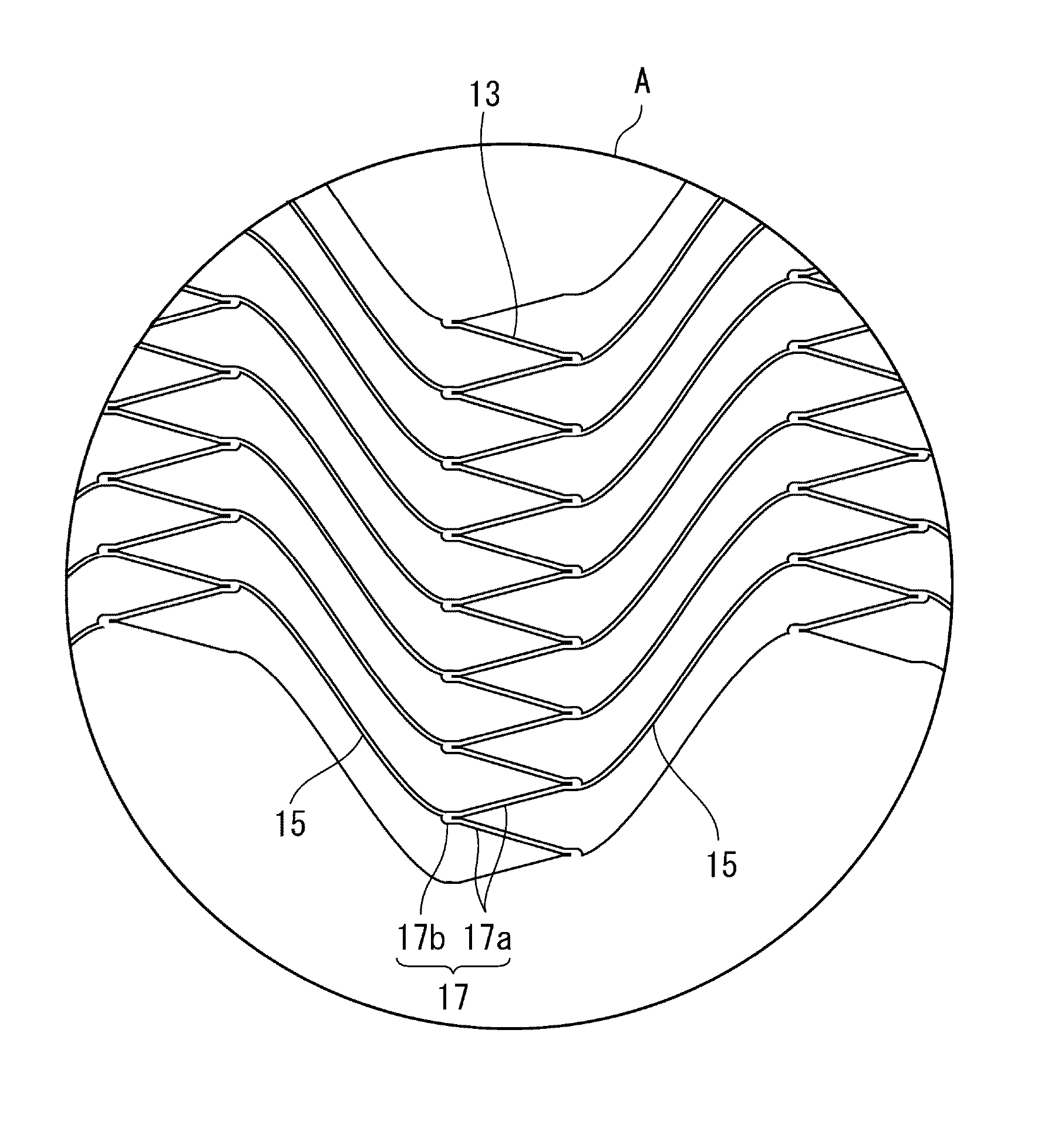
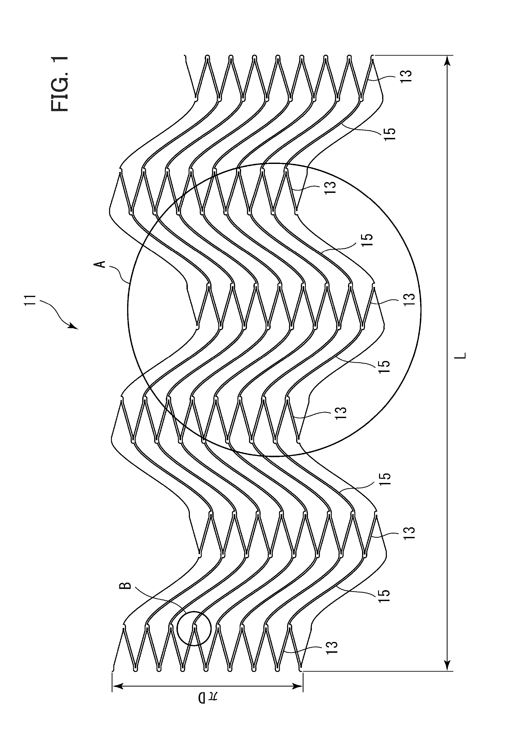
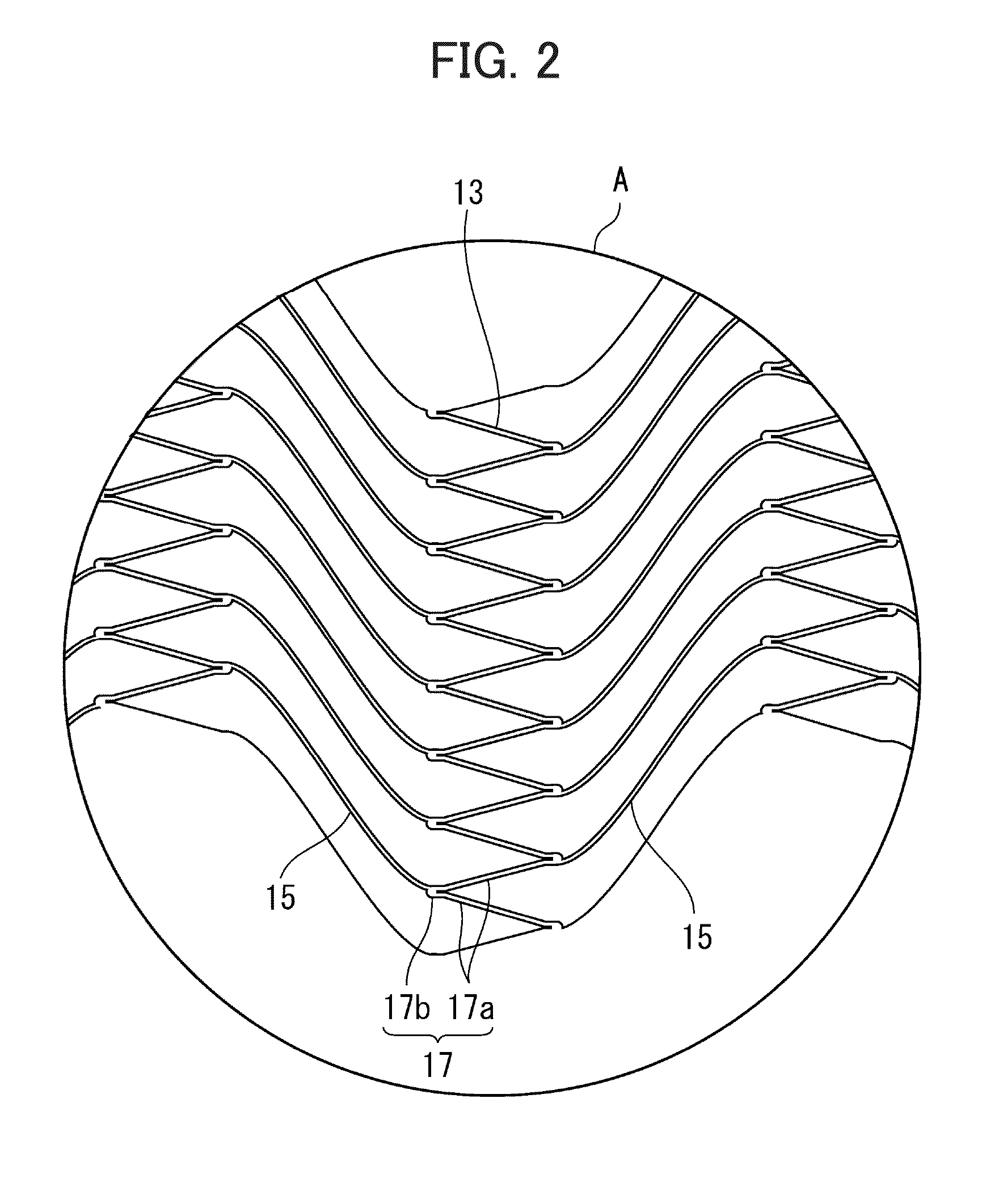
[0039]In the following, embodiments of a highly flexible stent according to the present invention are described with reference to the drawings. With reference to FIGS. 1 to 3, an overall configuration of a highly flexible stent 11 according to one embodiment of the present invention is described.

[0040]The stent 11 is of a substantially cylindrical shape, with the diameter thereof being D and the length in a longitudinal axis direction being L. A peripheral wall of the stent 11 has a structure of a mesh pattern in which a plurality of closed cells having a congruent shape surrounded by wire-shaped materials is covering a circumferential direction. In FIG. 1, for the purpose of facilitating understanding of the structure of the stent 11, the stent 11 is illustrated in a state expanded in a plane. Here, in the present specification, the peripheral wall of the stent 11 refers to a part that separates the inside from the outside of a cylinder with a substantially cylindrical shape of the...


PUM


Abstract

A stent has circular bodies having a wavy-line pattern and arranged side-by-side and coiled elements 15 arranged between the circular bodies that are adjacent and extending in a spiral manner, and apices on opposite sides of the wavy-line pattern of the circular bodies that are adjacent are connected by way of the coiled elements 15. A knob portion 19 is formed at each apex of the wavy-line pattern, and the knob portion 19 includes an extension portion 19a extending in the axis direction and a semicircle portion 19b formed at a tip of the extension portion, and the coiled element 15 is connected with the knob portion 19. A slit is formed at a part of the extension portion 19a of the knob portion 19, and the slit 21 extends in the axis direction from an inner peripheral portion at the apex of the wavy-line pattern of the circular body.

Description

[0001]This application is based on and claims the benefit of priority from Japanese Patent Application No. 2013-137130, filed on 28 Jun. 2013, the content of which is incorporated herein by reference.BACKGROUND OF THE INVENTION[0002]1. Field of the Invention[0003]The present invention relates to a highly flexible stent placed in a luminal structure of a living body in order to expand lumen.[0004]2. Related Art[0005]In a biological organ having a luminal structure such as blood vessels, the trachea and the intestines, when stenosis occurs therein, a cylinder-shaped stent with mesh pattern is used in order to secure patency at a site of pathology by expanding an inner cavity at a narrowed part. These biological organs often have bent or tapered structures locally (i.e. a tubular structure of which sectional diameters of the inner cavity differ locally in an axial direction). Therefore, a stent having higher conformability has been desired which can flexibly adapt to such a complex ves...

Claims


Application Information

Patent Timeline
Patent Type & Authority Patents(United States)
IPC IPC(8): A61F2/88A61F2/90
CPCA61F2/88A61F2/90A61F2/915A61F2002/91508A61F2002/91558A61F2002/91575A61F2250/0036
Inventor SHOBAYASHI, YASUHIRO
Owner OTSUKA MEDICAL DEVICES
Why Eureka
Try Eureka