Apparatus for producing alloy

a technology of apparatus and alloy, applied in the direction of manufacturing tools, magnetic bodies, transportation and packaging, etc., can solve the problems of reduced magnetic properties, partial defect of sintering, and formation of -fe in cast alloy, so as to improve the various properties of the obtained alloy, improve the coercive force, and improve the effect of coercive for

Active Publication Date: 2011-10-25
TDK CORPARATION
View PDF18 Cites 2 Cited by
  • Summary
  • Abstract
  • Description
  • Claims
  • Application Information

AI Technical Summary

Benefits of technology

[0025]The apparatus for producing an alloy according to the present invention includes a heat-retaining container for storing the cast alloy flakes supplied from the crushing device, a temperature retaining heater for maintaining the temperature of the cast alloy flakes in the heat-retaining container, and an inclination device for sending the cast alloy flakes in the heat-retaining container to the storage container by inclining the heat-retaining container. Therefore, it is possible to improve various properties of the obtained alloy by retaining the temperature of the cast alloy flakes after crushing.
[0026]In particular, when the alloy is the R-T-B-based alloy, the coercive force can be improved by retaining the temperature. Therefore, it is possible to produce a rare-earth element magnet having high coercive force without increasing the compositional ratio of Dy and Tb in the R-T-B-based alloy.

Problems solved by technology

When the distribution of the R-rich phase in a cast magnet is inferior, sintering may be partially defective, and magnetic properties may be decreased.
Another problem involved in casting of the R-T-B-based alloy is that α-Fe is formed in the cast alloy.
Due to this, α-Fe not only deteriorates crushing efficiency during the crushing of the alloy, but also changes the composition before and after crushing, and greatly affects the particle distribution.
In addition, if α-Fe remains even after sintering, magnetic characteristics of the sintered product are deteriorated.

Method used


Image

  • Apparatus for producing alloy
  • Apparatus for producing alloy
  • Apparatus for producing alloy

Examples


example

Example 1

[0134]In order to obtain a raw material, metal neodymium, metal dysprosium, ferroboron, cobalt, aluminum, copper, and iron were added to an aluminum crucible so that the raw material contained 28% of Nd, 4.5% of Dy, 0.96% of B, 1.0% of Co, 0.15% of Al, 0.10% of Cu, and the remainder of Fe as a mass ratio, and these were melted in a high frequency melting furnace in an argon gas atmosphere at 1 atm to prepare a molten alloy.

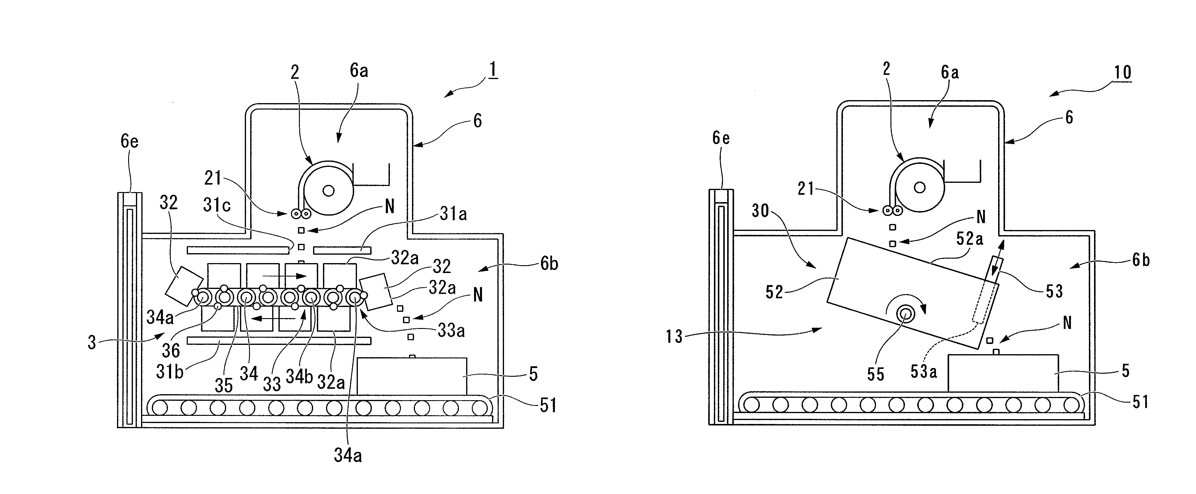
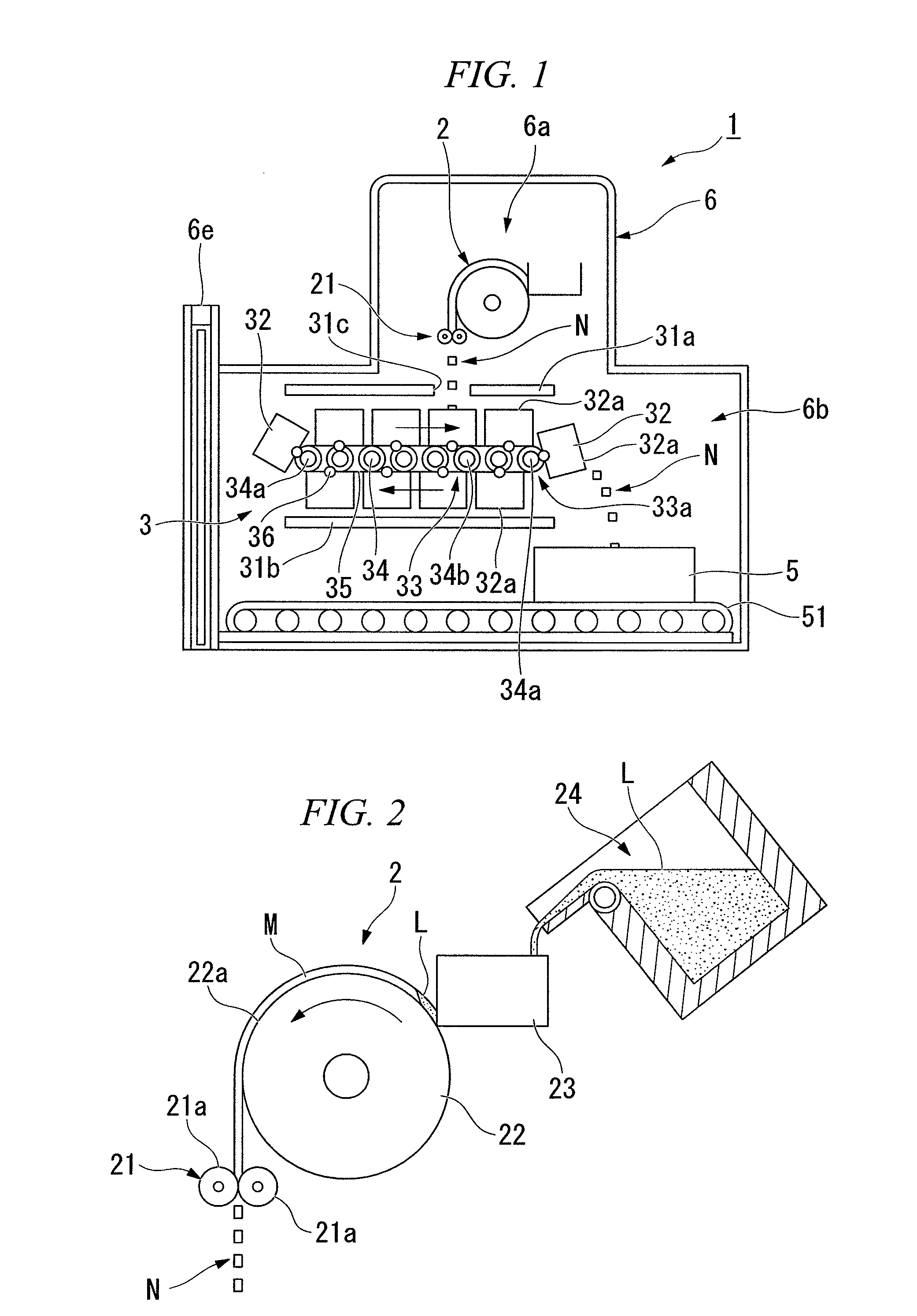
[0135]Subsequently, the molten alloy was supplied to the production apparatus shown in FIG. 1, and casted by the SC method, and the cast alloy flakes were produced.

[0136]Moreover, the diameter of the cooling roller was 600 mm, and the material constituting the cooling roller was an alloy containing a small amount of Cr and Zr, and Cu as the remainder. The inside of the cooling roller was cooled.

[0137]The rotating speed of the cooling roller during casting was 1.3 m / s. When the average temperature of the cast alloy when it was removed from the cooling roll...

example 2

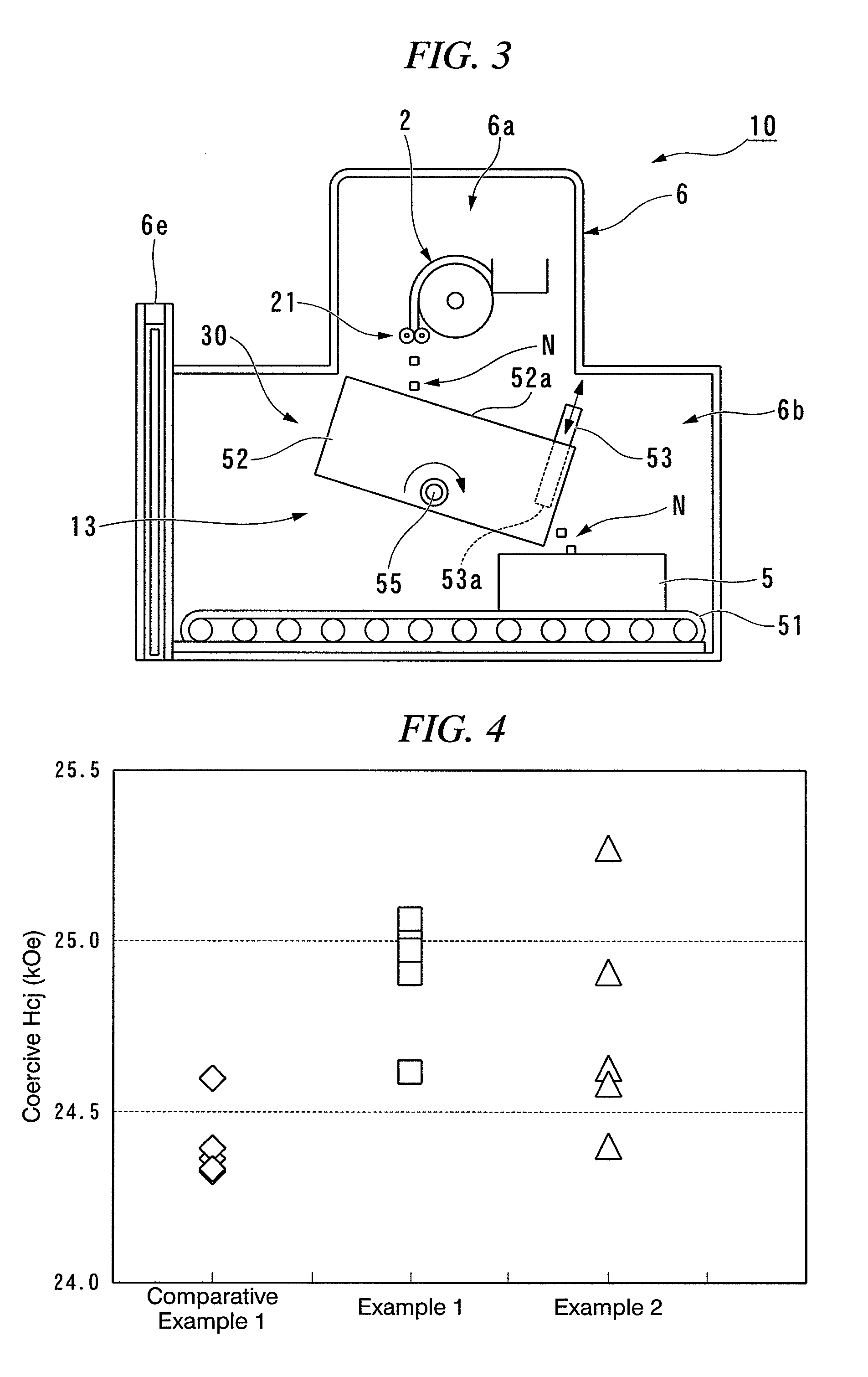
[0141]The cast alloy flakes of Example 2 were produced in a manner identical to that of Example 1, except that the cast alloy flakes were stored in the heat-retaining container 52 of the heat-retaining device 30 shown in FIG. 3, and the temperature was maintained at 800° C. for 2 minutes and 30 seconds on average.


PUM

PropertyMeasurementUnit
particle sizeaaaaaaaaaa
thicknessaaaaaaaaaa
diameteraaaaaaaaaa

Abstract

A production apparatus is provided which can produce an alloy which can produce a rare-earth magnet having high coercive force. The apparatus for producing an alloy is a device that includes at least a casting device for casting a molten alloy by a strip casting method, a crushing device for crushing cast alloy after casting, a heat-retaining device for maintaining temperature of cast alloy flakes N supplied from the crushing device, and a storage container for storing the cast alloy flakes N after maintaining the temperature. The heat-retaining device includes a heat-retaining container for storing the cast alloy flakes N supplied from the crushing device, a temperature retaining heater for maintaining the temperature of the cast alloy flakes N in the heat-retaining container, an inclination device for sending the cast alloy flakes N in the heat-retaining container to the storage container by inclining the heat-retaining container.

Description

FIELD OF THE INVENTION[0001]The present invention relates to an apparatus for producing an alloy. In particular, the present invention relates to an apparatus for producing a R-T-B-based rare-element containing alloy (R is at least one element of the rare-earth elements containing Y, T is metal which contains essentially Fe, and B is boron).[0002]Priority is claimed on Japanese Patent Application, No. 2007-247851, filed on Sep. 25, 2007, the contents of which are incorporated herein by reference in their entirety.BACKGROUND OF THE INVENTION[0003]R-T-B-based magnets, which have the maximum magnetic energy product in permanent magnets, are used for HD (hard disks), MRI (magnetic resonance imaging methods), various motors, etc. because they have high characteristics. In recent years, since saving energy has been increasingly demanded, in addition to an improvement of heat resistance of the R-T-B-based magnets, the use of R-T-B magnets as motors including a motor for vehicles has increa...

Claims


Application Information

Patent Timeline
Patent Type & Authority Patents(United States)
IPC IPC(8): B22D11/12B22D45/00B22F1/068B22F1/142
CPCB22F1/0055B22F1/0085C22C33/02B22D11/0611H01F1/0577H01F41/0266B22D11/126B22F2009/048C22C2202/02B22F1/068B22F1/142
Inventor NAKAJIMA, KENICHIRO
Owner TDK CORPARATION
Why Eureka
Try Eureka