Fiber composite component for absorbing energy

a composite material and energy-absorbing technology, applied in the direction of chemistry apparatus and processes, transportation and packaging, efficient propulsion technologies, etc., can solve the problems of large fuselage structure failures, sudden failures, and insufficient impact energy absorption in large regions of the fuselage structur

Active Publication Date: 2015-07-14
AIRBUS OPERATIONS GMBH
View PDF20 Cites 0 Cited by
  • Summary
  • Abstract
  • Description
  • Claims
  • Application Information

AI Technical Summary

Benefits of technology

[0007]Therefore, the object of the present invention is to provide a fiber composite component for absorbing energy in the event of a crash for an aircraft or spacecraft, a corresponding fuselage structure portion and an aircraft or spacecraft which no longer have, or significantly reduce the above-described drawbacks and provide further advantages.
[0013]In comparison with the approaches mentioned at the outset, the present invention therefore has inter alia the advantage that the use of a laminate made of a metal layer and CFRP layers combines the advantages of the two materials, namely the ductility of the metal and the high strength and low weight of the CFRP layers.
[0015]In a preferred arrangement, the at least one metal foil layer which is corrosion-resistant with respect to the CFRP layers extends in the longitudinal direction of the fiber composite component. As a result, forces which can occur during an impact are absorbed in that the ductile metal layer is deformed and owing to its high resilience inhibits a sudden rupturing or breaking of the fiber composite layers.

Problems solved by technology

Although the fiber composite material has a high strength, it can suddenly fail as a result of the action of forces during an impact.
In the event of a crash, this brittle behaviour has the result that large regions of the fuselage structure fail without absorbing impact energy to a sufficient extent.

Method used


Image

  • Fiber composite component for absorbing energy
  • Fiber composite component for absorbing energy
  • Fiber composite component for absorbing energy

Examples


Embodiment Construction

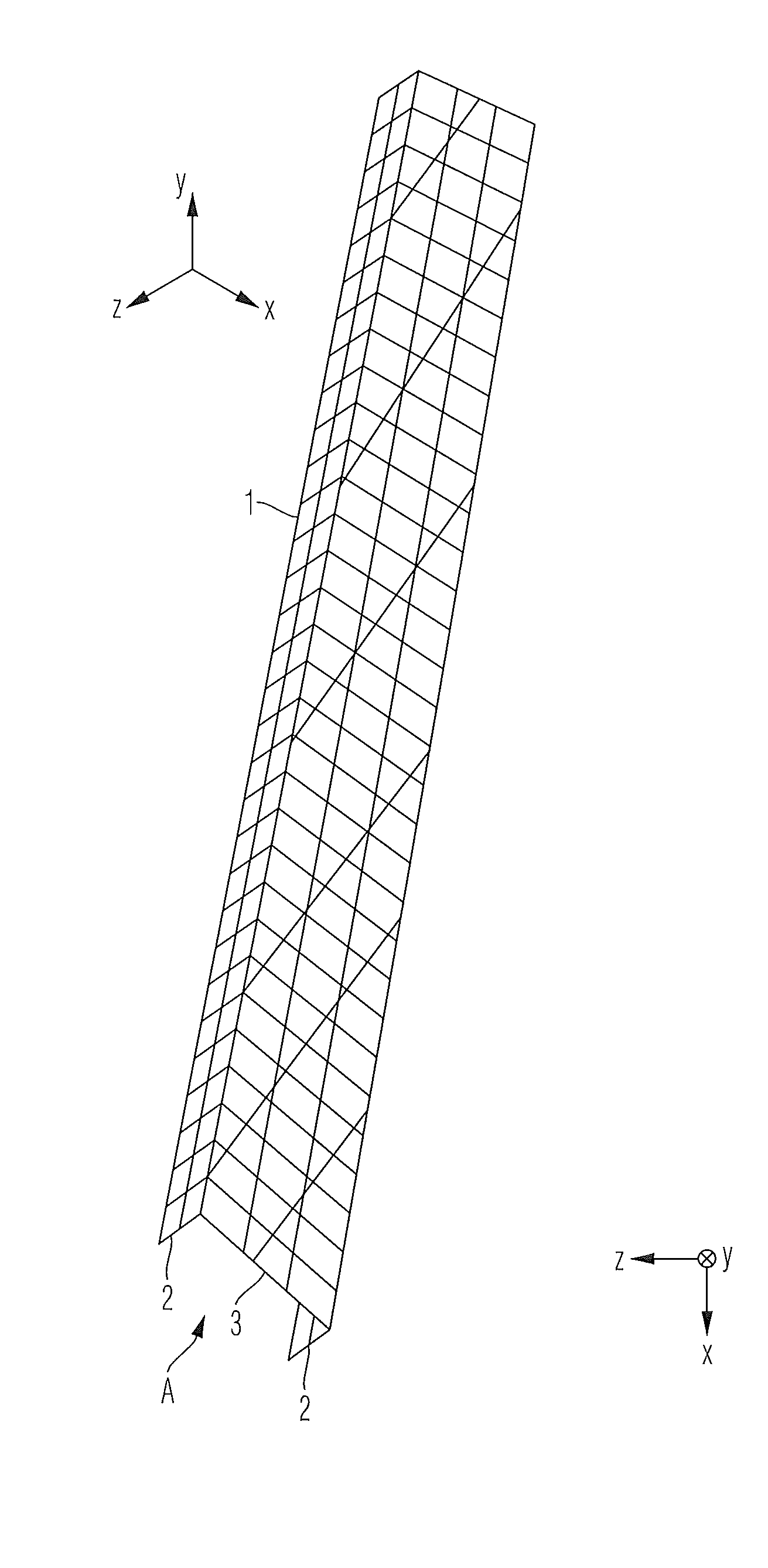
[0031]In the figures, like reference numerals denote like or functionally equivalent components, unless indicated otherwise. Coordinate systems x, y, z and x1, y1, z1 are also given in the figures to facilitate orientation.

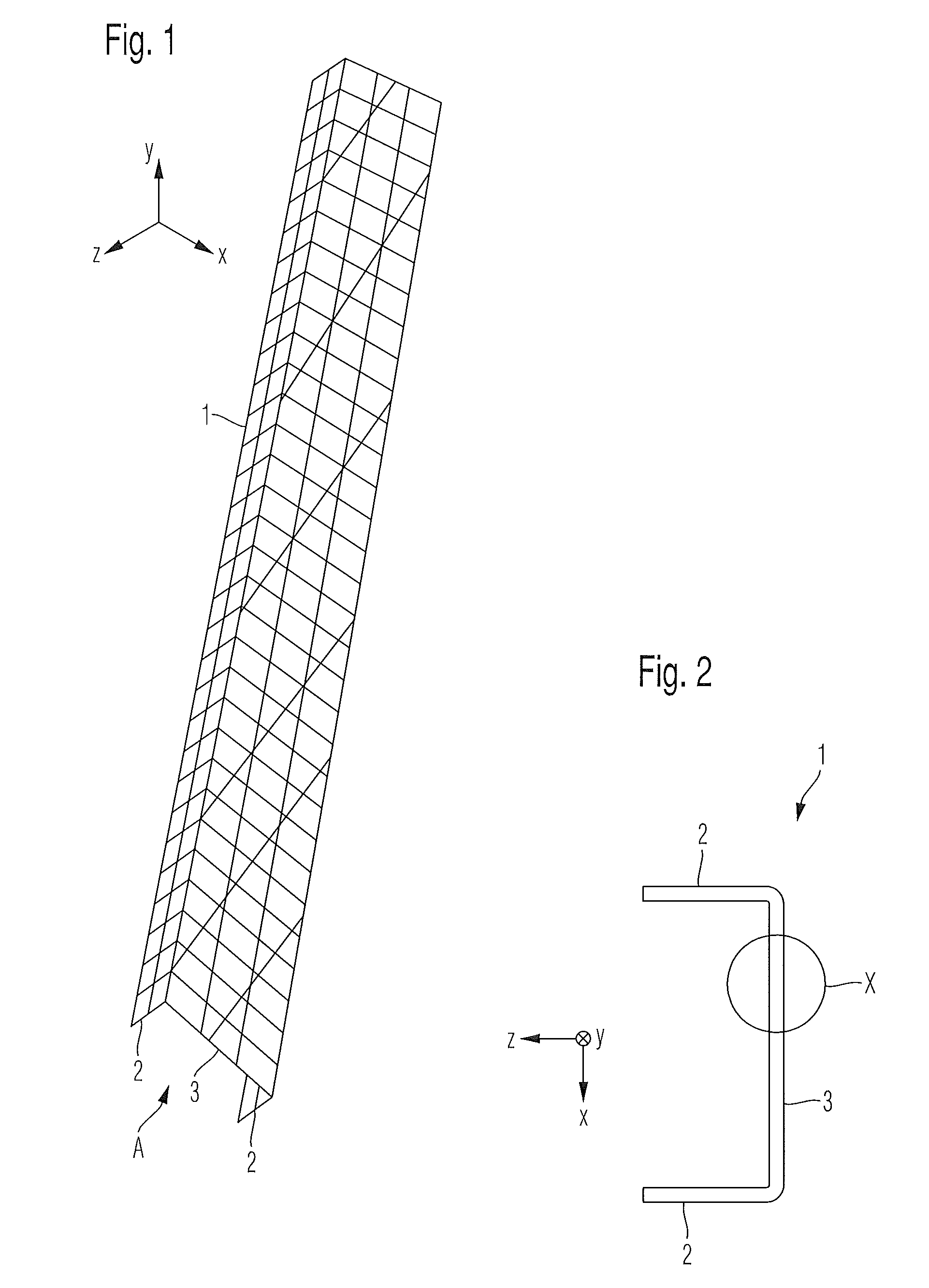
[0032]FIG. 1 is a perspective view of a first embodiment of a fiber composite component 1 according to the invention. This fiber composite component 1 has a U-shaped profile, as shown in FIG. 2 in a schematic view A of the first embodiment according to FIG. 1. A side portion 2 is applied substantially at right angles to a web 3 extending in the longitudinal direction (y-direction) of the fiber composite component 1 in each case. The side portions 2 extend in the longitudinal direction y and in a z-direction of the fiber composite component 1. A width in the x-direction of the web 3 decreases in the longitudinal direction of the fiber composite component 1, from the bottom to the top of FIG. 1.

[0033]The web 3 of the fiber composite component 1 comprises at least on...


PUM

PropertyMeasurementUnit
thicknessaaaaaaaaaa
thicknessaaaaaaaaaa
thicknessaaaaaaaaaa

Abstract

In the case of a fiber composite component for energy absorption in the event of a crash for an aircraft or spacecraft, the fiber composite component is formed as a laminate construction made of CFRP layers and at least one integrated metal foil portion which is corrosion-resistant with respect to the CFRP layers. A fuselage structure portion of an aircraft or spacecraft is formed using at least one fiber composite component of this type. An aircraft or spacecraft comprises a fuselage structure portion of this type.

Description

CROSS-REFERENCE TO RELATED APPLICATIONS[0001]This application is a continuation of PCT / EP2009 / 061264 filed Sep. 1, 2009 and claims the benefit of and priority to U.S. Provisional Application No. 61 / 100,935, filed Sep. 29, 2008 and German Patent Application No. 10 2008 042 452.8, filed Sep. 29, 2008, the entire disclosures of which are herein incorporated by reference.FIELD OF THE INVENTION[0002]The present invention relates to a fiber composite component of an aircraft or spacecraft, a fuselage structure portion and an aircraft or spacecraft.[0003]Although the present invention and the problem on which it is based can be applied to any fiber composite components, in the following they will be described in detail with reference to fiber composite components, in particular carbon fiber reinforced plastics material (CFRP) components, for example formers and support members of a fuselage structure of an aircraft.[0004]Fuselage structures in aircraft construction currently consist of rei...

Claims


Application Information

Patent Timeline
Patent Type & Authority Patents(United States)
IPC IPC(8): B32B3/24B32B1/00B64C1/06B32B3/26B32B15/08B64C1/00
CPCB64C1/062B32B1/00B32B3/266B32B15/08B32B2262/106B32B2307/558B32B2307/56B32B2307/714B32B2605/18B64C2001/0072Y02T50/433Y10T428/24132Y10T428/24331Y02T50/40
Inventor TACKE, STEFANROMING, THORSTEN
Owner AIRBUS OPERATIONS GMBH
Why Eureka
Try Eureka