
Rotor hub and blade root fairing apparatus and method

a technology of blade root fairing and rotor hub, which is applied in the direction of rotorcraft, aircraft, vehicles, etc., can solve the problems of stalling blade retreat, limited lift equalization due to flapping, and much more limited maximum flight speed of fixed wing aircraft. achieve the effect of sacrificing aerodynamic contouring

Active Publication Date: 2015-07-14
SKYWORKS GLOBAL INC
View PDF25 Cites 12 Cited by
  • Summary
  • Abstract
  • Description
  • Claims
  • Application Information

AI Technical Summary

Benefits of technology

The patent text discusses the issue of aerodynamic drag in aircraft and how it affects design. Flaps are added to fixed wing aircraft to increase lift, but they also increase drag. The text describes a fairing that provides a spherical interface between a blade and a hub, allowing for three degrees of freedom in blade movement without sacrificing aerodynamic contouring. The fairing has a seal to prevent airflow into the hub and maintains a thin region of air between the mated spherical surfaces. The technical effect of this design is reduced aerodynamic drag and increased lift without sacrificing performance.

Problems solved by technology

Although rotating wing aircraft provide the significant advantage of vertical takeoff and landing (VTOL), they are much more limited in their maximum flight speed than are fixed wing aircraft.
However, lift equalization due to flapping is limited by a phenomenon known as “retreating blade stall.” As noted above, flapping of the rotor blades increases the angle of attack of the retreating blade.
However, at certain higher speeds, the increase in the blade angle of attack required to equalize lift on the advancing and retreating blades results in loss of lift (stalling) of the retreating blade.
A second limit on the speed of rotating wing aircraft is the drag at the tips of the rotor.
In autogyro aircraft, the tips of the advancing blades are also subject to this increased drag, even for flight speeds much lower than the speed of sound.
Nevertheless, the same drag increase occurs eventually.
For example, if the blade angle of attack is upward with respect to wind velocity, but wind is moving over the wing in a reverse direction, the blade may experience negative lift.
As advance ratios increase, the drag caused by the rotor may be a significant consumer of power.

Method used


Image

  • Rotor hub and blade root fairing apparatus and method
  • Rotor hub and blade root fairing apparatus and method
  • Rotor hub and blade root fairing apparatus and method

Examples


Embodiment Construction

[0069]It will be readily understood that the components of the present invention, as generally described and illustrated in the drawings herein, could be arranged and designed in a wide variety of different configurations. Thus, the following more detailed description of the embodiments of the system and method of the present invention, as represented in the drawings, is not intended to limit the scope of the invention, as claimed, but is merely representative of various embodiments of the invention. The illustrated embodiments of the invention will be best understood by reference to the drawings, wherein like parts are designated by like numerals throughout.

[0070]This patent application hereby incorporates by reference U.S. Pat. No. 5,301,900 issued Apr. 12, 1994 to Groen et al., U.S. Pat. No. 1,947,901 issued Feb. 20, 1934 to J. De la Cierva, and U.S. Pat. No. 2,352,342 issued Jun. 27, 1944 to H. F. Pitcairn.

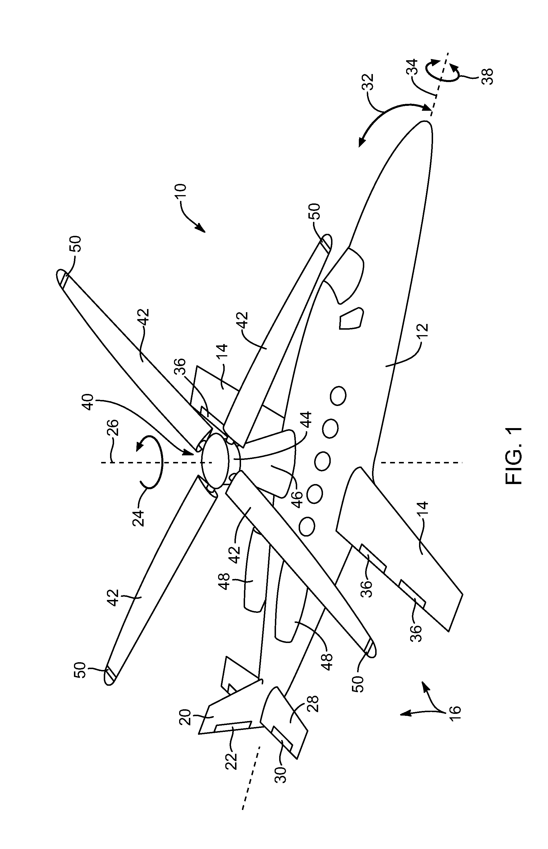
[0071]Referring to FIG. 1, an aircraft 10 includes an airframe 12 or a fu...


PUM


Abstract

A fairing system may be assembled about a rotor of a rotorcraft to present an aerodynamically quasi-static region that rotates in an airstream, as well as certain extensions that sweep through the airstream as the rotor hub passes through the air. A spherical interface between the extensions on the rotor hub fairing and the base or root portion of each blade fairing provides three degrees of freedom permitting lead-lag, flapping, and blade pitch pivoting in the blade, while still maintaining an aerodynamic profile that will minimize drag.

Description

RELATED APPLICATIONS[0001]This application claims the benefit of U.S. Provisional Patent Application Ser. No. 61 / 466,177, filed on Mar. 22, 2011, which is hereby incorporated by reference.[0002]Additionally, this patent application hereby incorporates by reference U.S. Pat. No. 5,301,900 issued Apr. 12, 1994 to Groen et al., U.S. Pat. No. 1,947,901 issued Feb. 20, 1934 to J. De la Cierva, and U.S. Pat. No. 2,352,342 issued Jun. 27, 1944 to H. F. Pitcairn.BACKGROUND[0003]1. The Field of the Invention[0004]This invention relates to rotating wing aircraft, and, more particularly to rotating wing aircraft relying on autorotation of a rotor to provide lift, and systems and methods for improving aerodynamics of a rotorcraft airframe.[0005]2. The Background Art[0006]Rotating wing aircraft rely on a rotating wing to provide lift. In contrast, fixed wing aircraft rely on air flow over a fixed wing to provide lift. Fixed wing aircraft must therefore achieve a minimum ground velocity on takeof...

Claims


Application Information

Patent Timeline
Patent Type & Authority Patents(United States)
IPC IPC(8): B64C27/48B64C27/32B64C27/02
CPCB64C27/48B64C27/025B64C27/32B64C7/00
Inventor VAN DER WESTHUIZEN, JACOB J.WHITE, ROBERT OWEN
Owner SKYWORKS GLOBAL INC
Learn More