Idling stop control device, vehicle and vehicle control method

a technology of idling stop and control device, which is applied in the direction of engine starters, machines/engines, transportation and packaging, etc., can solve the problems of frequent stop and restart of engines, and achieve the effect of improving the fuel consumption of the vehicl

Active Publication Date: 2015-07-14
TOYOTA JIDOSHA KK
View PDF10 Cites 5 Cited by
  • Summary
  • Abstract
  • Description
  • Claims
  • Application Information

AI Technical Summary

Benefits of technology

[0035]The invention may be implemented by a variety of aspects: for example, a control system and an automobile including the idle reduction control device described above, a manufacturing method and a manufacturing apparatus of the idle reduction control device, a computer program that causes the computer to implement the functions corresponding to the respective steps of the vehicle control method, a storage medium in which such a computer program is stored.

Problems solved by technology

Idle reduction in the case of a short stop time, for example, during a traffic jam causes a problem that a stop and a restart of the engine are repeated frequently.

Method used


Image

  • Idling stop control device, vehicle and vehicle control method
  • Idling stop control device, vehicle and vehicle control method
  • Idling stop control device, vehicle and vehicle control method

Examples


first embodiment

A. First Embodiment

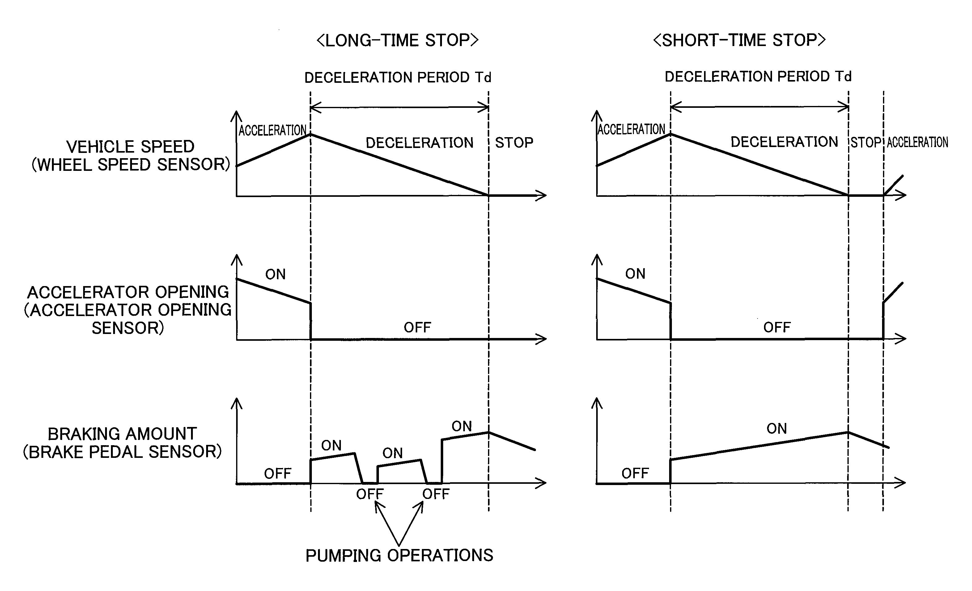
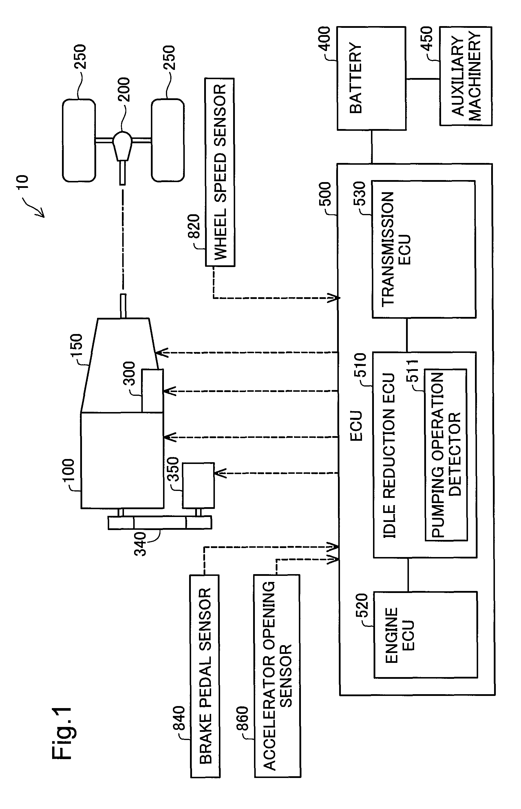
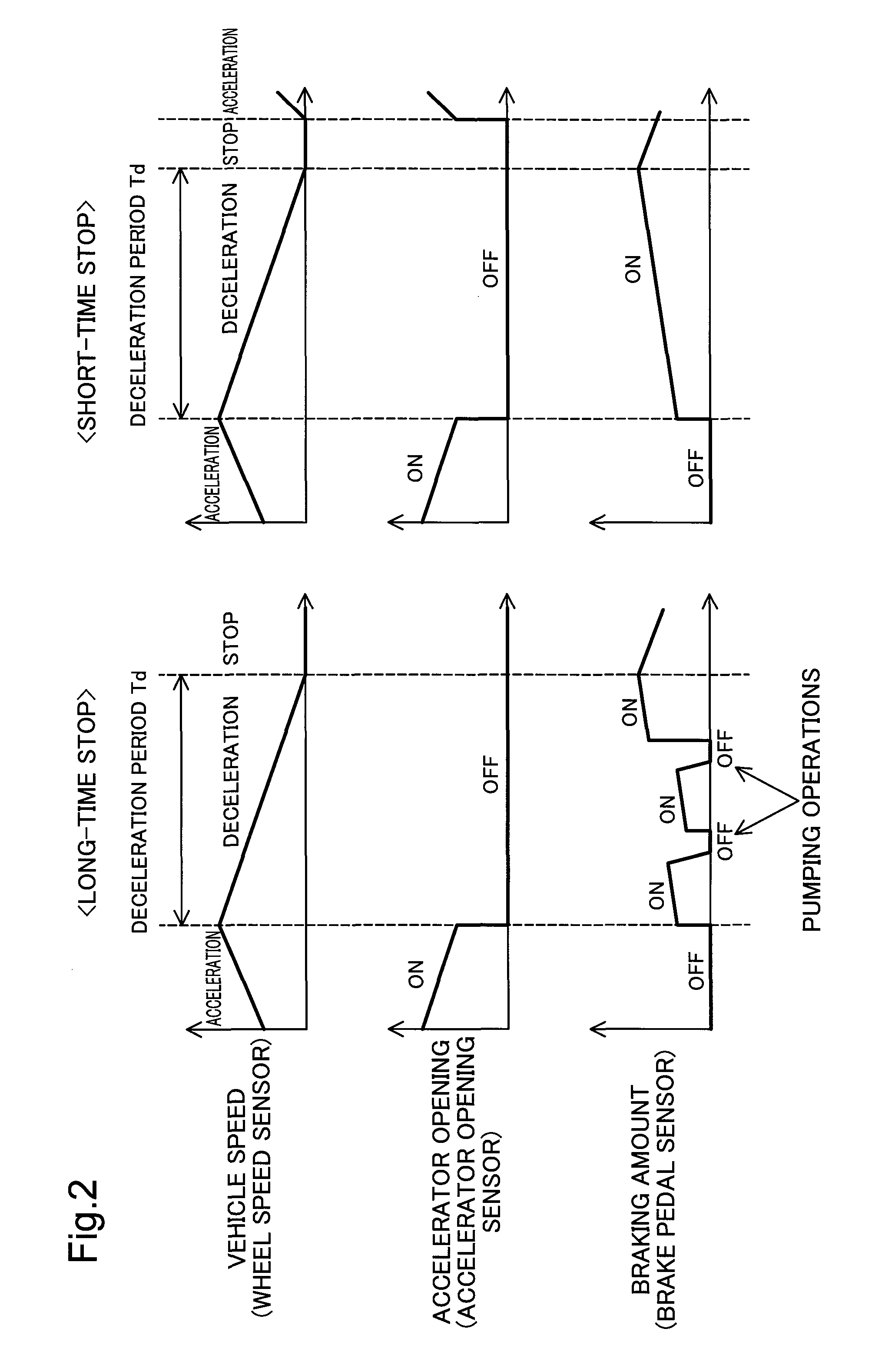
[0041]FIG. 1 is a diagram illustrating the configuration of an automobile 10 according to an embodiment of the invention. The automobile 10 is a vehicle having idle reduction function. The automobile 10 includes an engine 100, an automatic transmission 150, a differential gear 200, drive wheels 250, a starter 300, an alternator 350, a battery 400 and an electronic control unit (ECU) 500.

[0042]The engine 100 is an internal combustion engine that generates power by combustion of a fuel such as gasoline or light oil. The power of the engine 100 is transmitted to the automatic transmission 150, while being transmitted to the alternator 350 via a drive mechanism 340. The output of the engine 100 is changed according to the driver's accelerator pedal operation by the electronic control unit 500.

[0043]The automatic transmission 150 automatically changes the gear ratio (so-called gear shifting). The power (rotation speed·torque) of the engine 100 is subjected to gear shif...

second embodiment

B. Second Embodiment

[0068]A second embodiment describes a configuration of the idle reduction control (FIGS. 3 and 4) that varies the waiting time Tw according to the count value Nc. The general configuration of the automobile 10 is the same as that of the first embodiment and is thus not specifically described here. The idle reduction ECU 510 of the second embodiment stores an Nc-Tw relation table representing a relationship between the count value Nc and the waiting time Tw in the ROM.

[0069]FIG. 5 is a diagram illustrating the details of the Nc-Tw relation table. The abscissa of FIG. 5 shows the count value Nc, and the ordinate shows the waiting time Tw. As shown in FIG. 5, the Nc-Tw relation table is arranged such that the waiting time Tw decreases with an increase in count value Nc. For example, the Nc-Tw relation table is arranged, such that the waiting time Tw is 5 [s] at the count value Nc of 0 and is 1 [s] at the count value Nc of 5. In idle reduction control of the second e...

modification 1

C-1. Modification 1

[0072]According to the above embodiments, the idle reduction ECU 510 determines whether the automobile 10 stops at step S106 in idle reduction control (FIG. 3). Alternatively, the idle reduction control may determine whether the speed of the automobile 10 is reduced to or below a predetermined speed (>0). In other words, the idle reduction ECU 510 may stop the engine 100 in the state that the automobile 10 does not stop. In this modification, at step S108, the idle reduction ECU 510 may define the waiting time Tw as a time elapsed since the speed of the automobile 10 goes down to the predetermined speed or may define as a time elapsed since a stop of the automobile 10.


PUM


Abstract

An idle reduction control device mounted on a vehicle equipped with an engine and a brake comprises: a pumping operation detector that detects a pumping operation of the brake; and an engine controller that controls a start and a stop of the engine. The engine controller stops the engine after elapse of a predetermined time since a stop of the vehicle, when a number of the pumping operations during a deceleration period before the stop of the vehicle is less than a predetermined value.

Description

CROSS-REFERENCE TO RELATED APPLICATIONS[0001]This is a national phase application based on the PCT International Patent Application No. PCT / JP2011 / 007013 filed Dec. 15, 2011, the entire contents of which are incorporated herein by reference.TECHNICAL FIELD[0002]The present invention relates to an idle reduction control device mounted on a vehicle equipped with an engine and a brake, a vehicle equipped with an engine and a brake and a vehicle control method of controlling a vehicle equipped with an engine and a brake.BACKGROUND ART[0003]In the prior art, idle reduction has been known to stop an engine during a stop of a vehicle, such as an automobile, and restart the engine at the time of starting the vehicle, in order to reduce fuel consumption and gas emission during the stop of the vehicle. It is preferable to perform idle reduction when the automobile stops for a relatively long time, for example, when the automobile stops at a traffic light. Idle reduction in the case of a short...

Claims


Application Information

Patent Timeline
Patent Type & Authority Patents(United States)
IPC IPC(8): F02M3/00F02M3/02F02N11/08F02D17/04F02D29/02B60W30/18
CPCF02M3/02B60W30/18072B60W30/18136F02D17/04F02D29/02F02N11/0822B60W2540/12B60Y2300/46F02N2200/102Y02T10/48Y02T10/40
Inventor MATSUNAGA, MASAKIMORIMURA, JUNICHIKIDO, YASUNARI
Owner TOYOTA JIDOSHA KK
Why Eureka
Try Eureka