Power system for a vehicle

A technology of power system and vehicle, applied in the field of power system, can solve the problems of not being able to idle, reduce the control, shorten the duration of the engine stop state, etc.

Active Publication Date: 2015-04-22
DENSO CORP +1
View PDF7 Cites 6 Cited by
  • Summary
  • Abstract
  • Description
  • Claims
  • Application Information

AI Technical Summary

Problems solved by technology

In this case, the duration of the engine stop state is shortened, so that the idling reduction control cannot be effectively performed

Method used


Image

  • Power system for a vehicle
  • Power system for a vehicle
  • Power system for a vehicle

Examples


no. 1 example

[0021] refer to Figure 1 to Figure 4 A first embodiment of the electric power system for a vehicle of the present invention is described. The power system of this embodiment is an in-vehicle power system installed and used in a vehicle. The vehicle runs using an engine (internal combustion engine) as a drive source. When starting the engine, the starter motor is driven to initially rotate the engine.

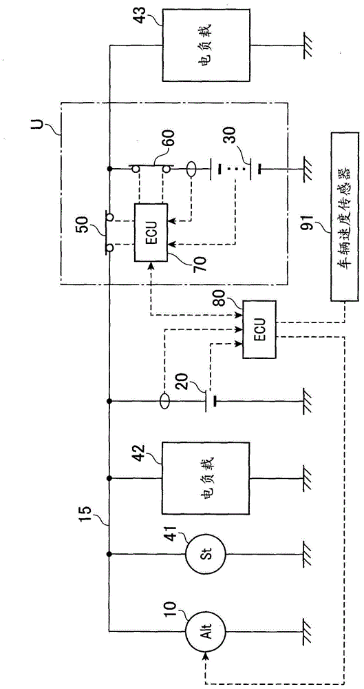
[0022] figure 1 is a schematic diagram showing the power system according to the first embodiment. Such as figure 1 As shown in , the power system includes: alternator 10 , lead storage battery 20 , lithium ion battery 30 , electric loads 41 , 42 and 43 , MOS switch 50 and SMR switch 60 . The lead storage battery 20, the lithium ion battery 30, and the electric loads 41, 42, and 43 are electrically connected in parallel with the alternator 10 (generator) via the power feeder 15 (connection cable). The power feeder 15 forms a feed path so that power is fed from the alterna...

no. 2 example

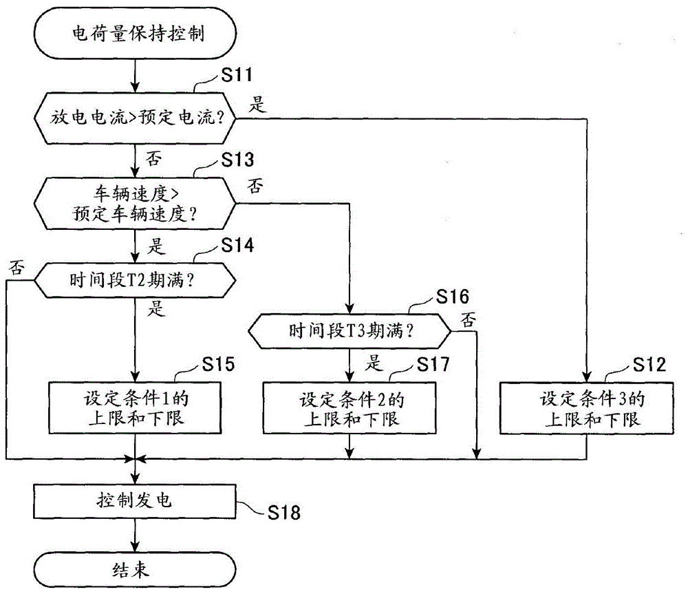
[0064] now refer to Figure 5 to Figure 7 , the second embodiment of the present invention is described hereinafter. In the second embodiment, in image 3 The charge retention control shown in is changed to Figure 6 The amount of charge shown in is kept under control. The rest of the configuration is similar to the first embodiment. It should be understood that in the second embodiment and in the modified examples described hereafter, in order to omit unnecessary description, the components or steps of the control process that are the same as or similar to those in the first embodiment The steps are given the same reference numerals.

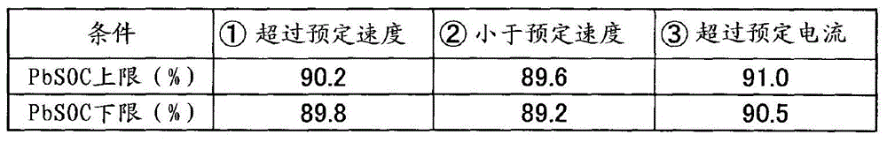
[0065] Figure 5 is a table showing upper and lower limits of PbSOC for several conditions according to the second embodiment. Such as Figure 5 As shown in , in the second embodiment, an appropriate range of PbSOC is finely set according to several conditions. Such as Figure 5 As shown in , in a state where the engine is in operation...


PUM


Abstract

A power system for a vehicle is provided, in which idle reduction control is performed, under which an engine is automatically stopped when a predetermined automatic stop condition is met, and automatically restarted when a predetermined restart condition is met in a state where the engine is automatically stopped. The power system includes a generator which is driven on the basis of output of the engine, a battery which is connected to the generator, and a controller which allows the generator to generate power when an amount of charge of the battery has decreased below a lower limit, and which sets the lower limit to a higher level when the speed of the vehicle has exceeded a predetermined speed than in a case where a speed of the vehicle has not exceeded the predetermined speed.

Description

technical field [0001] The present invention relates to an electrical system for a vehicle comprising a generator and a battery. Background technique [0002] A known electric power system installed in a vehicle is configured by using two batteries, namely, a lead storage battery and a lithium ion battery. By appropriately using these batteries, electric power is supplied to various electric loads installed in the vehicle. For example, Patent Document JP-A-2012-080706 discloses a specific configuration of an electric power system in which a lithium ion battery is electrically connected to a generator and a lead storage battery via a semiconductor switch. [0003] The configuration disclosed in JP-A-2012-080706 realizes idle reduce control. Under the idling reduction control, the engine is automatically stopped when a predetermined automatic stop condition is satisfied, and the engine is automatically restarted when a predetermined restart condition is satisfied in a state ...

Claims


Application Information

Patent Timeline
Patent Type & Authority Applications(China)
IPC IPC(8): H02J7/14B60R16/03B60R16/033B60R16/04H02J7/16
CPCB60R16/03H02J7/1446H02J7/0078Y02T10/92H02J2310/46H02J7/00714
Inventor 片山直树齐藤成则片冈准驹田节子
Owner DENSO CORP
Why Eureka
Try Eureka