Hybrid vehicle drive idle reduction system and method

A vehicle drive and vehicle technology, applied in the field of hybrid vehicle drive system, can solve the problems of increasing cost and complexity, and achieve the effect of reducing complexity and reducing fuel consumption

Active Publication Date: 2015-05-13
POWER TECH HLDG LLC
View PDF12 Cites 6 Cited by
  • Summary
  • Abstract
  • Description
  • Claims
  • Application Information

AI Technical Summary

Problems solved by technology

Advanced powertrain control systems and power management systems required to operate hybrid vehicle propulsion systems add cost and complexity

Method used


Image

  • Hybrid vehicle drive idle reduction system and method
  • Hybrid vehicle drive idle reduction system and method
  • Hybrid vehicle drive idle reduction system and method

Examples


Embodiment Construction

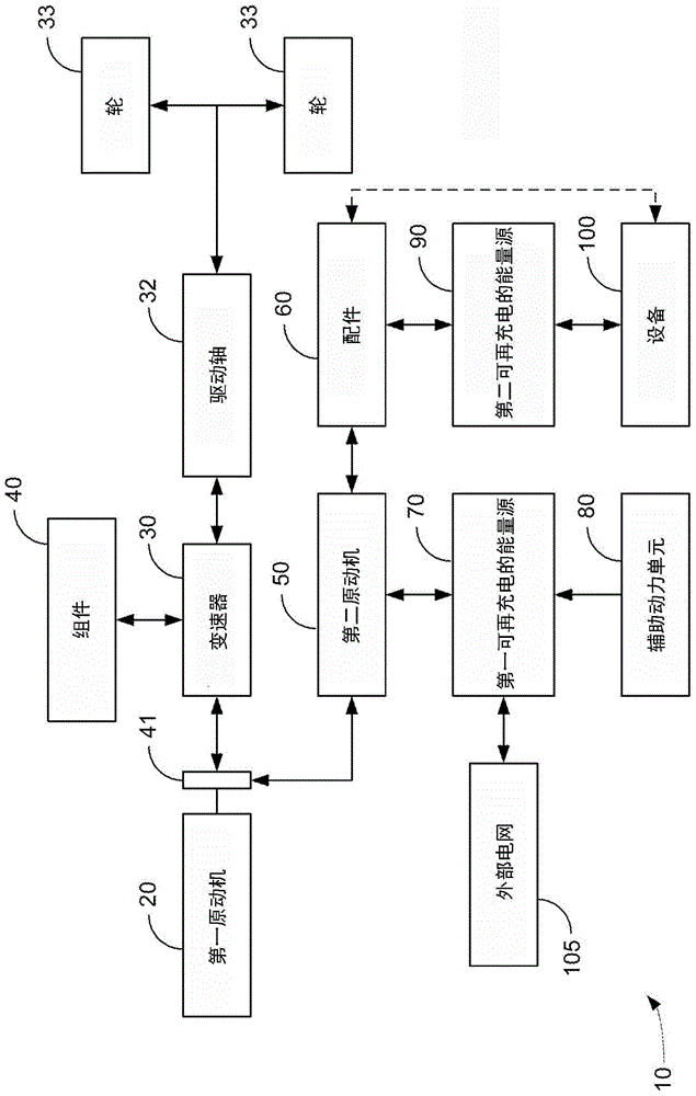
[0035] A hybrid vehicle drive system according to several possible embodiments is presented. It is a feature of an exemplary embodiment of a hybrid vehicle drive system that the hybrid drive system may utilize an interface between a first prime mover and a transmission without using a PTO. It is another feature of one embodiment that the drive shaft may be powered solely by the first prime mover, the second prime mover, and accessories using the interface, or any combination thereof. A preferred embodiment incorporates a hydraulic system into the hybrid vehicle drive system to optimize energy storage and use. It should be noted that the term "motor" as used herein refers to a motor / generator or a motor / pump, and is not limited to devices that only perform motor operations.

[0036] According to one embodiment, inefficiency during regenerative braking is caused by removing the first prime mover from the system when the vehicle is braking. Yet another feature of an exemplary e...


PUM


Abstract

A vehicle drive system for a vehicle includes a first prime mover, a first prime mover driven transmission, and a rechargeable power source. The vehicle drive system includes an electric motor and direct or indirect mechanical communication with the first prime mover. Wherein the electric motor can receive power from the first prime mover driven transmission and can receive power from the first prime mover. The vehicle drive system also includes a control system that causes the electric motor to rotate the first prime mover at a speed higher than an idle set point of the first prime mover while the vehicle is stopped, thereby reducing fuel consumption at idle per the vehicle.

Description

[0001] Cross references to related patent applications [0002] This application claims the benefit and priority of U.S. Provisional Application Serial No. 61 / 624118 (096637-0143) filed April 13, 2012 by Dalum, entitled "HYBRID VEHICLE DRIVE SYSTEM AND METHOD AND IDLE REDUCTION SYSTEM AND METHOD USING AN INTERFACE (Hybrid Vehicle Propulsion System and Method Using Interface and Idling Reduction System and Method)", and the US provisional application is incorporated herein by reference in its entirety. [0003] This application is related to the following applications: [0004] U.S. Application Serial No. 13 / 812,723, filed March 20, 2012, which claims priority to Provisional Application No. 61 / 566,526; [0005] PCT US2012 / 029835, filed March 20, 2012, claiming priority from provisional application No. 61 / 566,526; [0006] U.S. Patent Application No. 12 / 710247, filed February 22, 2010, which: [0007] - is a continuation-in-part of U.S. Patent Application No. 12 / 130,888 filed ...

Claims


Application Information

Patent Timeline
Patent Type & Authority Applications(China)
IPC IPC(8): B60W20/00B60W10/08B60W30/18B60K17/28B60K6/48
CPCB60K6/48B60K17/28B60W10/08B60W30/18054B60Y2300/64Y02T10/62B60W20/19B60W2710/0644H02J7/1415H02J7/0048B28C5/422H02J2310/48
Inventor 约瑟夫·T·达伦
Owner POWER TECH HLDG LLC
Why Eureka
Try Eureka