
Manufacturing method for semiconductor package, semiconductor package, and semiconductor device

a manufacturing method and semiconductor technology, applied in semiconductor devices, semiconductor/solid-state device details, electrical apparatus, etc., can solve the problems of difficult to maintain the electrical connection between the substrate and the semiconductor element, reduce the reliability of the electrical connection, and the solder pitch is too high, so as to achieve high-precision the formation of the circuit

Inactive Publication Date: 2015-07-14
PANASONIC CORP
View PDF10 Cites 1 Cited by
  • Summary
  • Abstract
  • Description
  • Claims
  • Application Information

AI Technical Summary

Benefits of technology

The present invention provides a method for making a semiconductor package that can accurately create circuits on an insulating layer covering a semiconductor element and create vias for electrically connecting the circuits to the semiconductor element. The invention also includes a semiconductor package made using this method and a semiconductor device that uses this package.

Problems solved by technology

Therefore, with the refining of the semiconductor package, the following limitations are required in narrowing a pitch of the solder bumps.
This makes it difficult to maintain the electrical connection between the substrate and the semiconductor element and decreases the reliability of the electrical connection.
Further, even when further refining of the semiconductor package is requested, in order to secure the electrical connection between the semiconductor element and the substrate, there is a limit in reducing an amount of solder.
Therefore, there is a limit in reducing the size of the solder bumps.
Electrical short circuit tends to occur.
Therefore, there is a limit in increasing the number of solder bumps (the number of terminals) with respect to the size of a semiconductor chip.
A connection failure due to the occurrence of the warp also tends to occur when the pitch of the solder bumps is narrowed by the refining of the semiconductor package.
Consequently, there is a limit in the narrowing of the pitch of the solder bumps and there is a limit in the refining of the semiconductor package.

Method used


Image

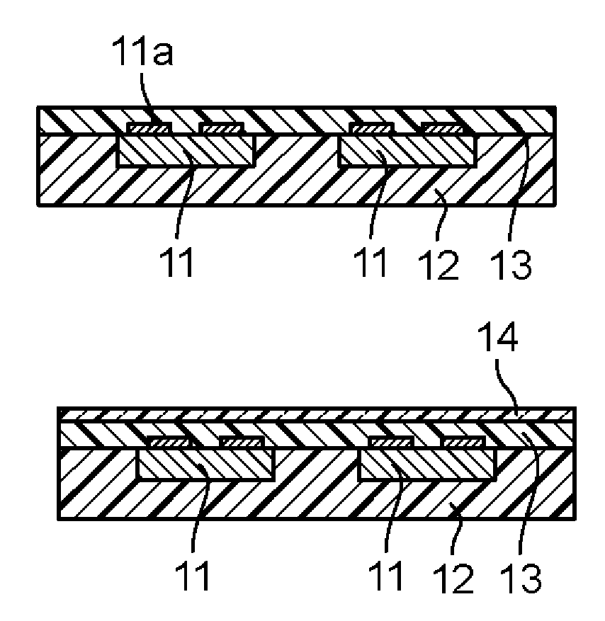
  • Manufacturing method for semiconductor package, semiconductor package, and semiconductor device
  • Manufacturing method for semiconductor package, semiconductor package, and semiconductor device
  • Manufacturing method for semiconductor package, semiconductor package, and semiconductor device

Examples


second embodiment

[0045]the present invention is explained.

[0046]A manufacturing method for a semiconductor package according to this embodiment is not specifically limited as long as the manufacturing method is a method including the steps as explained above. Examples of the manufacturing method for a semiconductor package according to this embodiment include a manufacturing method in which the covering step is a step of embedding the semiconductor element in the covering insulating layer. Specifically, the manufacturing method for a semiconductor package according to the second embodiment of the present invention is a manufacturing method for a semiconductor package including a covering step of forming a covering insulating layer that covers to embed a semiconductor element including electrodes on the principal plane thereof, a film-forming step of forming a resin film on the surface of the covering insulating layer on the electrodes side of the semiconductor element, a circuit pattern-forming step...

fourth embodiment

[0122]the present invention is explained.

[0123]Examples of a manufacturing method for a semiconductor package according to this embodiment include a manufacturing method in which the covering step is a step of forming, as the covering insulating layer, a covering insulating layer having projections of a predetermined shape on the surface of the semiconductor element on the electrodes side and the circuit pattern-forming step is a step of forming, as the circuit groove, a circuit groove reaching the surfaces of the projections and coupled to the recesses. Specifically, the manufacturing method for a semiconductor package according to the fourth embodiment of the present invention includes a covering step of forming a covering insulating layer that covers to embed a semiconductor element including electrodes on the principal plane thereof and has projections of a predetermined shape on the surface of the semiconductor element on the electrodes side, a film-forming step of forming a re...


PUM


Abstract

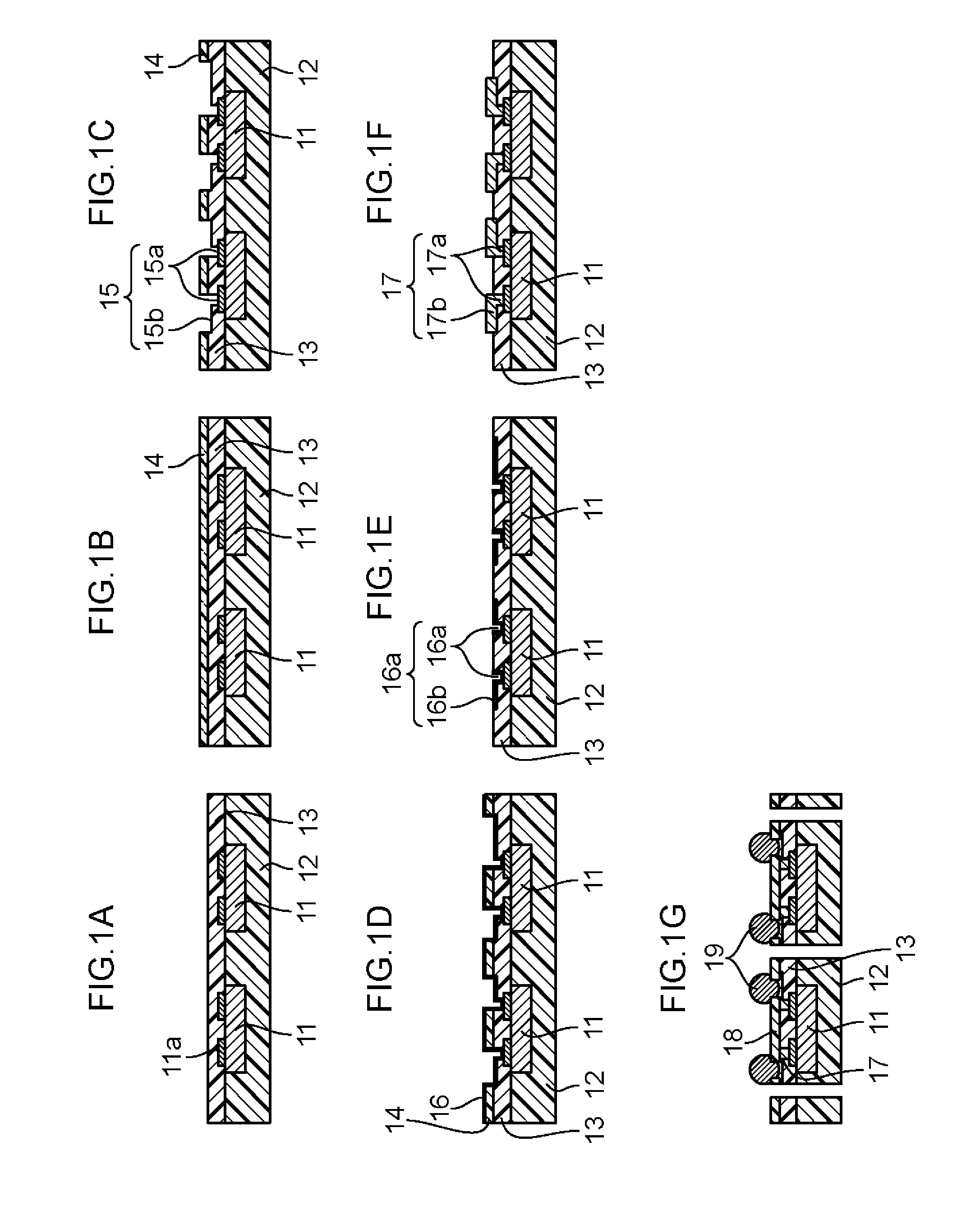
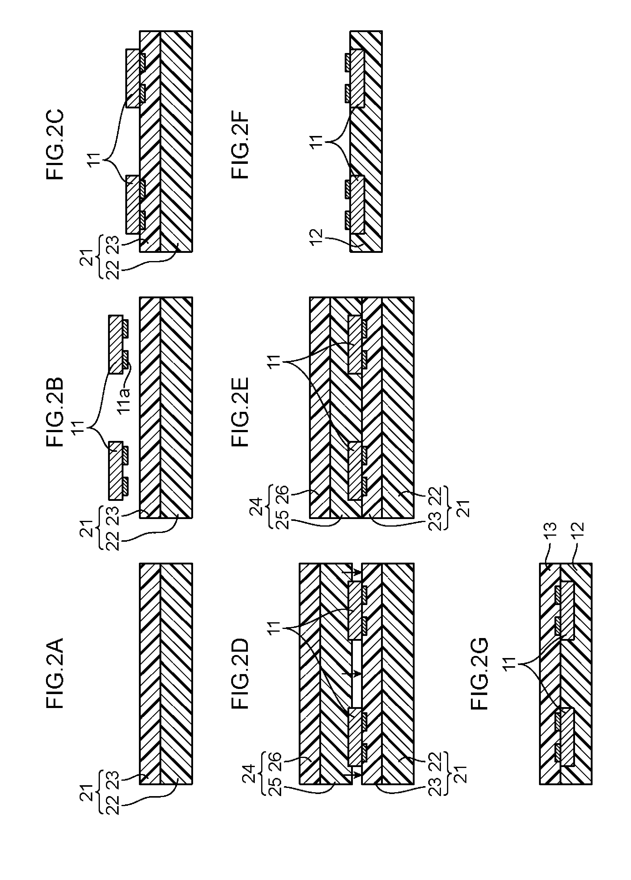
One aspect of the present invention resides in a manufacturing method for a semiconductor package, including a covering step of forming a covering insulating layer that covers the surface of a semiconductor element, a film-forming step of forming a resin film on the surface of the covering insulating layer, a circuit pattern-forming step of forming a circuit pattern portion including recesses reaching the surfaces of electrodes of the semiconductor element and a circuit groove having a desired shape and a desired depth, a catalyst-depositing step of depositing a plating catalyst or a precursor thereof on the surface of the circuit pattern portion, a film-separating step of separating the resin film from the covering insulating layer, and a plating processing step of forming a circuit electrically connected to the electrodes, by applying electroless plating to the covering insulating layer, from which the resin film is separated.

Description

RELATED APPLICATIONS[0001]This application is a national phase application of the U.S. National Phase under 35 U.S.C. §371 of International Application No. PCT / JP2012 / 006675, filed on Oct. 18, 2012, which in turn claims the benefit of Japanese Application No. 2011-229496, filed on Oct. 19, 2011, Japanese Application No. 2011-244785, filed on Nov. 8, 2011, and Japanese Application No. 2011-244786, filed on Nov. 8, 2011, the disclosures of which Applications are incorporated by reference herein.TECHNICAL FIELD[0002]The present invention relates to a manufacturing method for a semiconductor package, a semiconductor package obtained by the manufacturing method, and a semiconductor device including the semiconductor package.BACKGROUND ART[0003]A conventional semiconductor package generally had a configuration in which electrical connection between a semiconductor element and a substrate is secured by flip-chip mounting of electrodes of the semiconductor element such as a semiconductor ch...

Claims


Application Information

Patent Timeline
Patent Type & Authority Patents(United States)
IPC IPC(8): H01L21/00H01L23/48H01L23/498H01L23/538H01L23/31H01L21/56H01L21/768H01L23/00
CPCH01L21/76877H01L21/56H01L21/561H01L21/568H01L23/3114H01L23/481H01L23/49816H01L23/5389H01L24/03H01L24/96H01L24/05H01L24/11H01L24/13H01L2224/0236H01L2224/02311H01L2224/02379H01L2224/033H01L2224/0347H01L2224/03464H01L2224/0401H01L2224/04105H01L2224/05548H01L2224/12105H01L2224/131H01L2224/13022H01L2224/13023H01L2224/13024H01L2224/1411H01L2224/19H01L2224/2101H01L2224/2105H01L2224/96H01L2924/0001H01L2924/014H01L2224/13099H01L2924/00012H01L2224/03H01L2224/11H01L2924/18162H01L2924/15787H01L2924/15788H01L24/97H01L2924/12042H01L2924/3511H01L2924/00
Inventor TAKASHITA, HIROMITSUTAKEDA, TSUYOSHIKASHIHARA, KEIKOFUJIWARA, HIROAKIYOSHIOKA, SHINGO
Owner PANASONIC CORP
Learn More