Method of determining processing position in charged particle beam apparatus, and infrared microscope used in the method
- Summary
- Abstract
- Description
- Claims
- Application Information
AI Technical Summary
Benefits of technology
Problems solved by technology
Method used
Image
Examples
Embodiment Construction
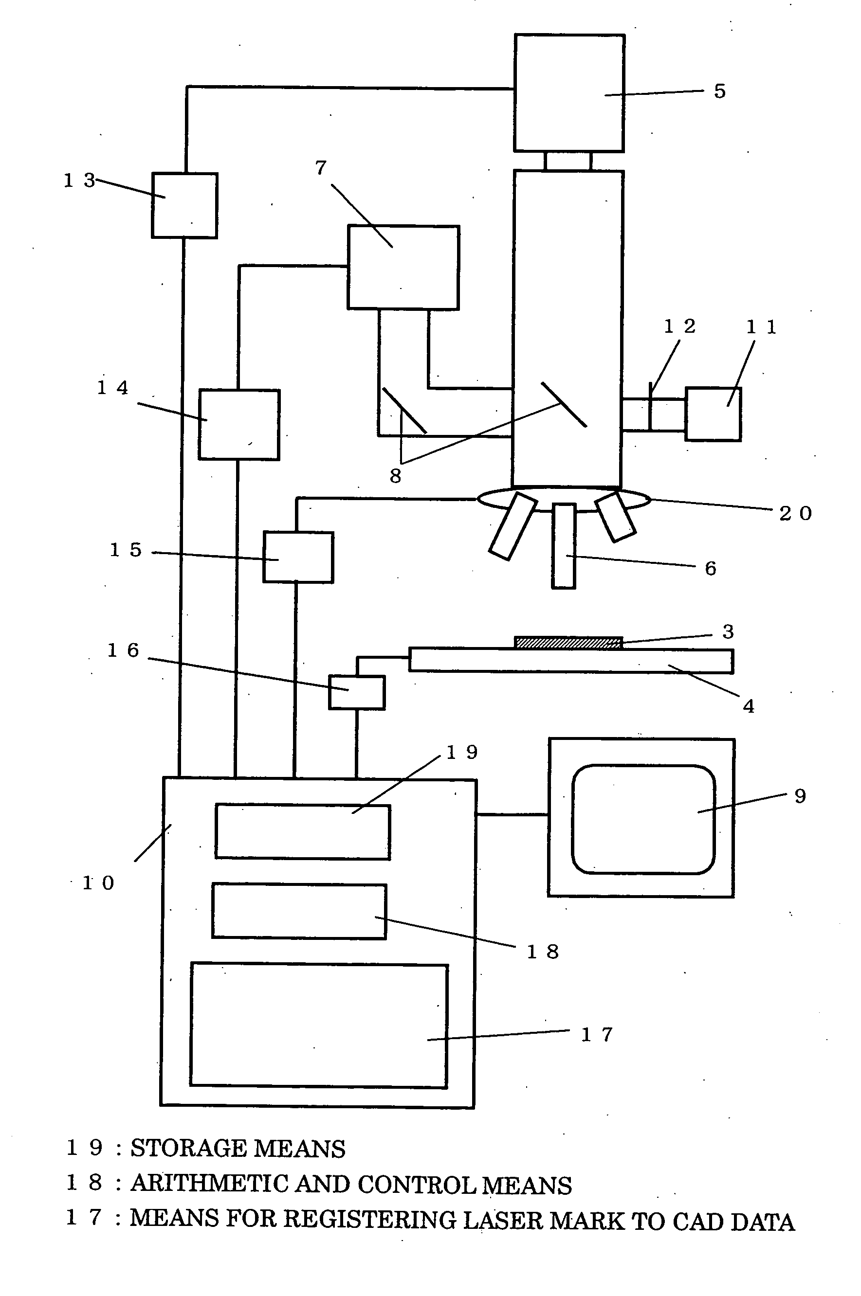
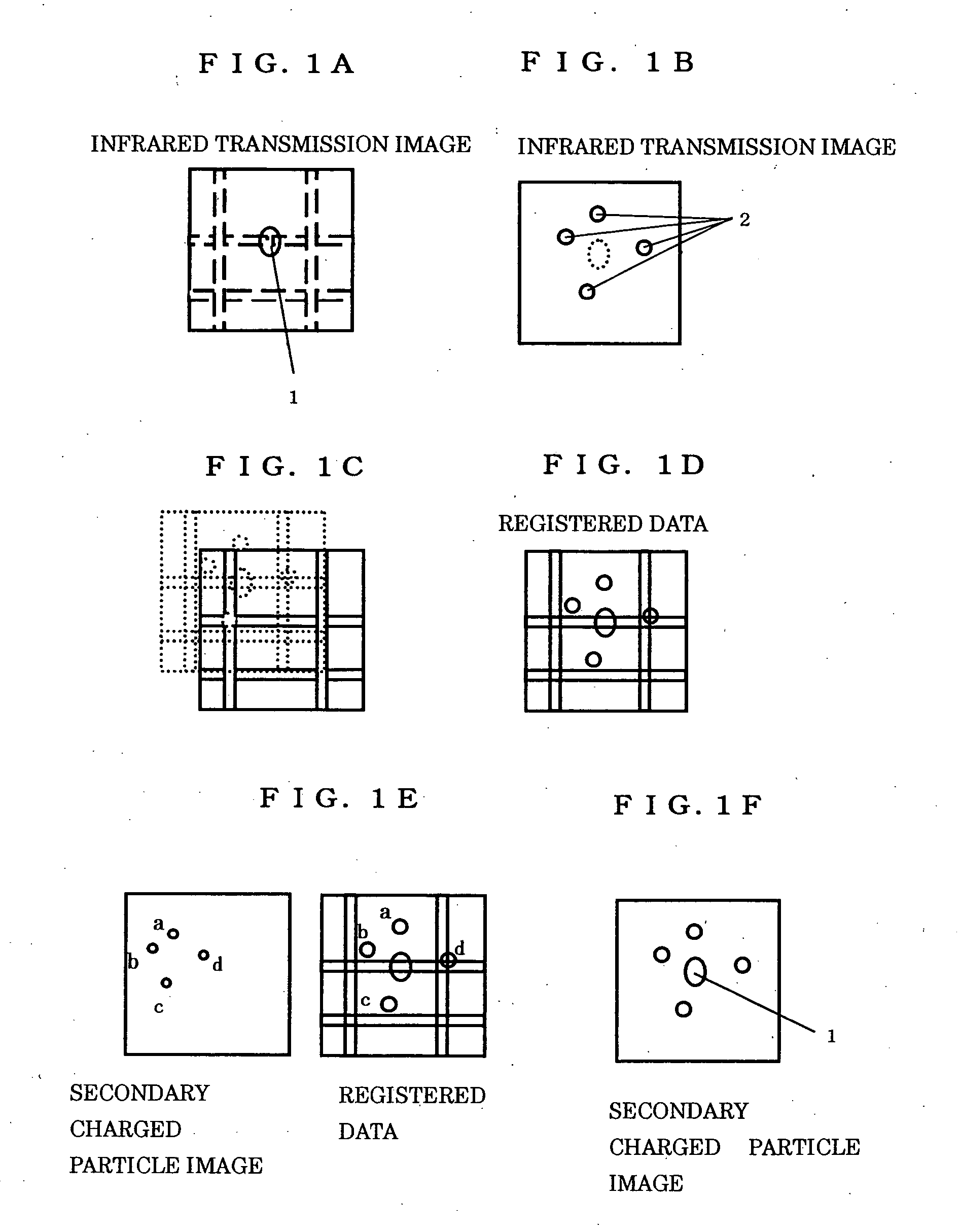
[0017] An embodiment of the present invention will here be explained by referring to the drawings. FIG. 1 is one showing figures of a sample in various steps of the processing positioning in the charged particle beam apparatus utilizing the infrared microscope and the CAD data. The steps comprise:
[0018] (A) 1st step: finding the processing / observation area 1 by an observation by the infrared microscope from the back face of the sample (FIG. 1A),
[0019] (B) 2nd step: for the setting mark of the secondary charged particle image in the charged particle beam apparatus, performing a laser marking 2 at the periphery of the processing / observation object area by the laser optical system disposed coaxially with the infrared microscope (FIG. 1B),
[0020] (C) 3rd step: superimposing the CAD data and the infrared transmission image at the periphery of the processing / observation area by using a software for CAD data processing and by an alignment between a transmission image (broken line portion...
PUM
 Abstract
Description
Claims
Application Information
 - R&D
- Intellectual Property
- Life Sciences
- Materials
- Tech Scout
- Unparalleled Data Quality
- Higher Quality Content
- 60% Fewer Hallucinations
Browse by: Latest US Patents, China's latest patents, Technical Efficacy Thesaurus, Application Domain, Technology Topic, Popular Technical Reports.
© 2025 PatSnap. All rights reserved.Legal|Privacy policy|Modern Slavery Act Transparency Statement|Sitemap|About US| Contact US: help@patsnap.com


