
Method of determining processing position in charged particle beam apparatus, and infrared microscope used in the method

a technology of charged particle beam and processing position, which is applied in the field of method of determining processing position in charged particle beam apparatus, and infrared microscope used in the method, can solve the problems of inability to perform lasers, inability to observe the processing area by visible light optical microscopes, etc., and achieves the effect of high accuracy and convenient processing positioning

Active Publication Date: 2008-12-02
HITACHI HIGH TECH SCI CORP
View PDF7 Cites 4 Cited by
  • Summary
  • Abstract
  • Description
  • Claims
  • Application Information

AI Technical Summary

Benefits of technology

The present invention provides a method for identifying and positioning a processing / observation area on a sample surface using an infrared microscope and a laser marking system. This allows for accurate processing positioning even when there is no characteristic shape present on the sample surface. The method also involves forming a deposition film on the sample surface and observing it using the infrared microscope and laser marking system. This allows for the observation of wiring layers and other features in the sample. The use of CAD data and the superposition of transmission images and registered data further enhances the accuracy of processing positioning.

Problems solved by technology

In the conventional processing positioning, in a case where the processing / observation area exists below the sample surface and an upper layer is not a transparent film like an insulating film, there has been the problem that the processing area cannot be observed by a visible light optical microscope.
Further, there have been the problems that, even in the case where the surface is a transparent film like the insulating film and the processing / observation object area can be observed by the visible light optical microscope, it is impossible to perform a laser marking because there exists no absorption of the laser beam in the insulating film and, in a case where no characteristic shape exists on the sample surface, the superposition cannot be performed by the secondary charged particle image and the visible light optical microscope image, by which only the sample surface can be observed.

Method used


Image

  • Method of determining processing position in charged particle beam apparatus, and infrared microscope used in the method
  • Method of determining processing position in charged particle beam apparatus, and infrared microscope used in the method
  • Method of determining processing position in charged particle beam apparatus, and infrared microscope used in the method

Examples


Embodiment Construction

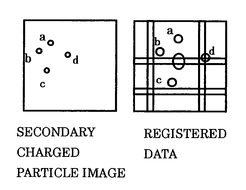
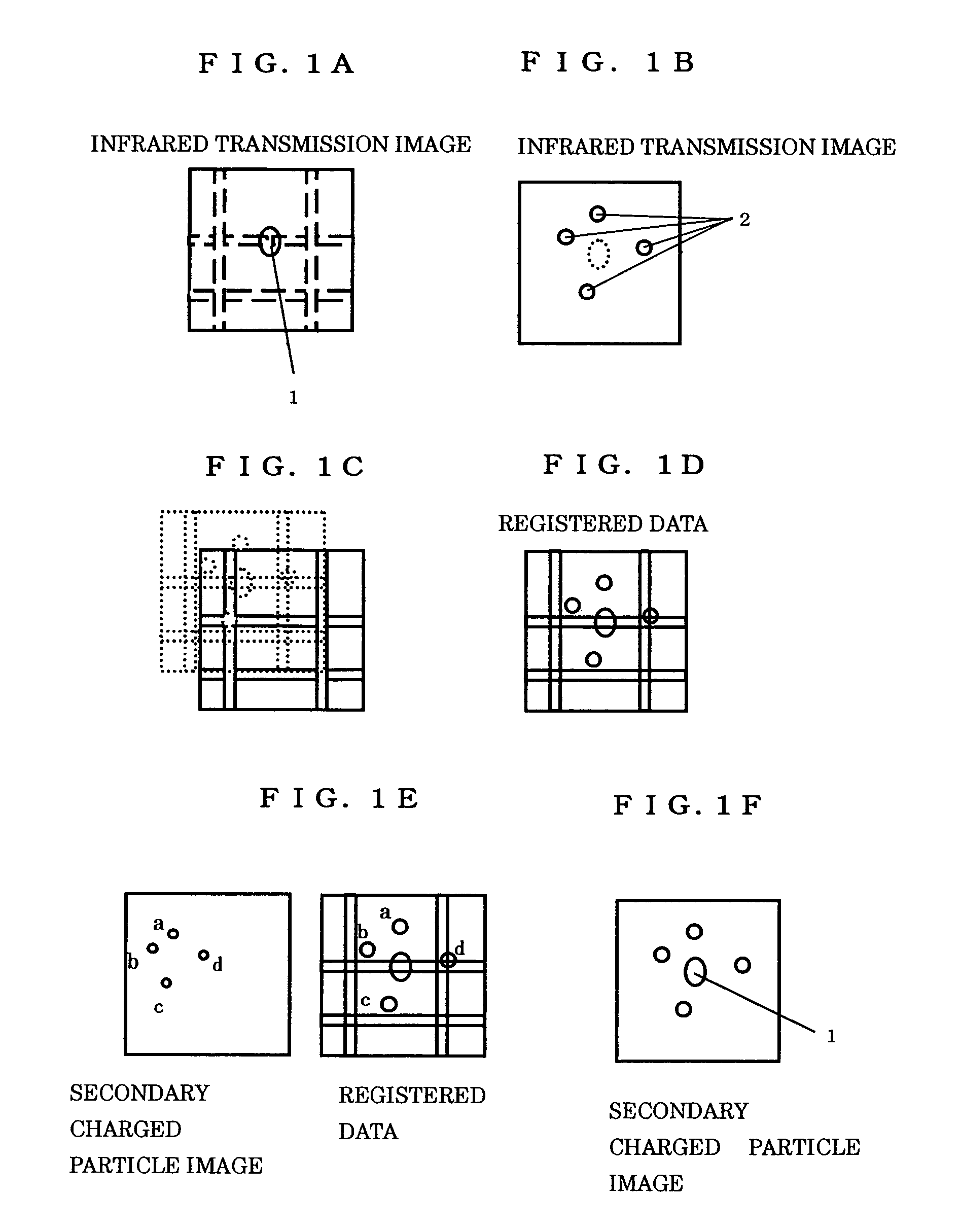
[0017]An embodiment of the present invention will here be explained by referring to the drawings. FIG. 1 is one showing figures of a sample in various steps of the processing positioning in the charged particle beam apparatus utilizing the infrared microscope and the CAD data. The steps comprise:

[0018](A) 1st step: finding the processing / observation area 1 by an observation by the infrared microscope from the back face of the sample (FIG. 1A),

[0019](B) 2nd step: for the setting mark of the secondary charged particle image in the charged particle beam apparatus, performing a laser marking 2 at the periphery of the processing / observation object area by the laser optical system disposed coaxially with the infrared microscope (FIG. 1B),

[0020](C) 3rd step: superimposing the CAD data and the infrared transmission image at the periphery of the processing / observation area by using a software for CAD data processing and by an alignment between a transmission image (broken line portion) by th...


PUM

PropertyMeasurementUnit
infrared microscopeaaaaaaaaaa
transmission imageaaaaaaaaaa
infrared transmissionaaaaaaaaaa

Abstract

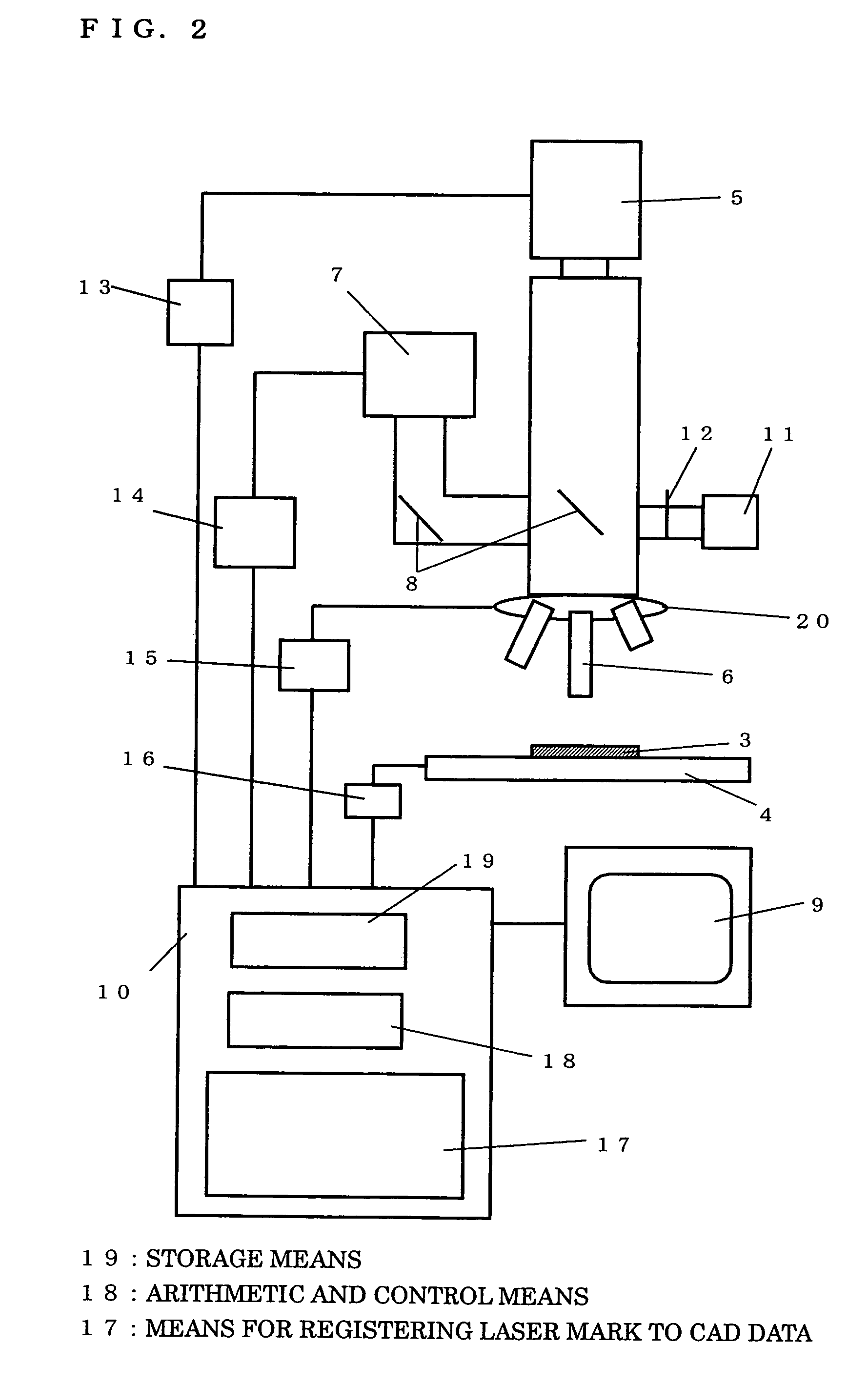
A laser mark which will be the positioning mark for a secondary charged particle image in the charged particle beam apparatus is applied by moving the sample processing / observation area in the charged particle beam apparatus so as to come into the view field while performing an observation by an infrared microscope, and by a using a laser optical system disposed coaxially with an optical observation system, the mark made at the periphery of the processing / observation object area. Next, by a superposition of an infrared transmission image and a CAD data, the processing / observation object area and the laser mark are registered onto the CAD data. And, by a correlation of the registered data read from the charged particle beam apparatus and the secondary charged particle image, it is possible to accurately and easily determine the processing position.

Description

[0001]This application claims priority under 35 U.S.C. §119 to Japanese Patent Application No. 2004-341729 filed Nov. 26, 2004, the entire content of which is hereby incorporated by reference.BACKGROUND[0002]The present invention relates to a method determining the processing position of a charged particle beam apparatus such as focused ion beam apparatus (FIB) and scanning electron microscope, and relates especially to a method of determining a processing position below the sample surface, which cannot be seen by a visible light optical microscope, and a laser microscope used in the method.[0003]In a processing positioning in a conventional charged particle beam apparatus, the processing position has been determined by a superposition of a visible light optical microscope image and a secondary charged particle image by a charged particle beam irradiation (for example, refer to Patent Document 1). Or, the processing position has been determined by performing a marking by a laser opt...

Claims


Application Information

Patent Timeline
Patent Type & Authority Patents(United States)
IPC IPC(8): G01J1/00G01N21/00G01N23/00
CPCG01N23/225H01J2237/317
Inventor KIYOHARA, MASAHIROSATO, MAKOTOASAHATA, TATSUYA
Owner HITACHI HIGH TECH SCI CORP
Learn More