Test device and test method for active noise reduction headphone

a test device and noise reduction technology, applied in the field of headphone production and testing, can solve the problems of increasing test cost, noise pollution to the surrounding environment, and high requirements for low frequency noise of noise sources, so as to reduce the complexity of the test, reduce the background noise, and effectively isolate the noise pollution of the noise source from the surrounding environment

Active Publication Date: 2015-07-14
GOERTEK INC
View PDF6 Cites 7 Cited by
  • Summary
  • Abstract
  • Description
  • Claims
  • Application Information

AI Technical Summary

Benefits of technology

[0010]In view of this, the present invention provides a test device and test method for a noise reduction headphone so as to solve the problem of noise pollution caused by high-power external noise source to the surrounding environment during the test process of noise reduction amount of the headphone, and moreover, test complexity is not increased.
[0022]Such a technical solution of the present invention can seal the sound emitted by the noise source within the enclosed cavity, thereby effectively isolating noise pollution of the noise source from the surrounding environment. Meanwhile, since the test panel can cooperate with the noise reduction headphone to form a coupling cavity in the test, and the sound of the noise source in the enclosed cavity can be transferred to the coupling cavity through the sound guiding hole in the common part of the test panel with the enclosed cavity. So the special shielding room is no longer required, and the requirement on the test environment is relieved, i.e., it is unnecessary to require a lower background noise of the test environment and no other noise sources, thereby the complexity of the test is reduced.

Problems solved by technology

In particular, in the test on a product line, the background noise in the production plant is generally high, and is concentrically distributed in low frequency range, and thus the requirement on low frequency noise of the noise source is higher, which increases test cost and brings large noise pollution.
Therefore, a critical difficulty in implementing the above test solution is the external noise source requires large enough power and low enough frequency, and such a test system may cause noise pollution to the surrounding environment.
However, in this way, the demand condition of the test is further increased, i.e., the complexity of the test is increased.

Method used


Image

  • Test device and test method for active noise reduction headphone
  • Test device and test method for active noise reduction headphone
  • Test device and test method for active noise reduction headphone

Examples


embodiment 1

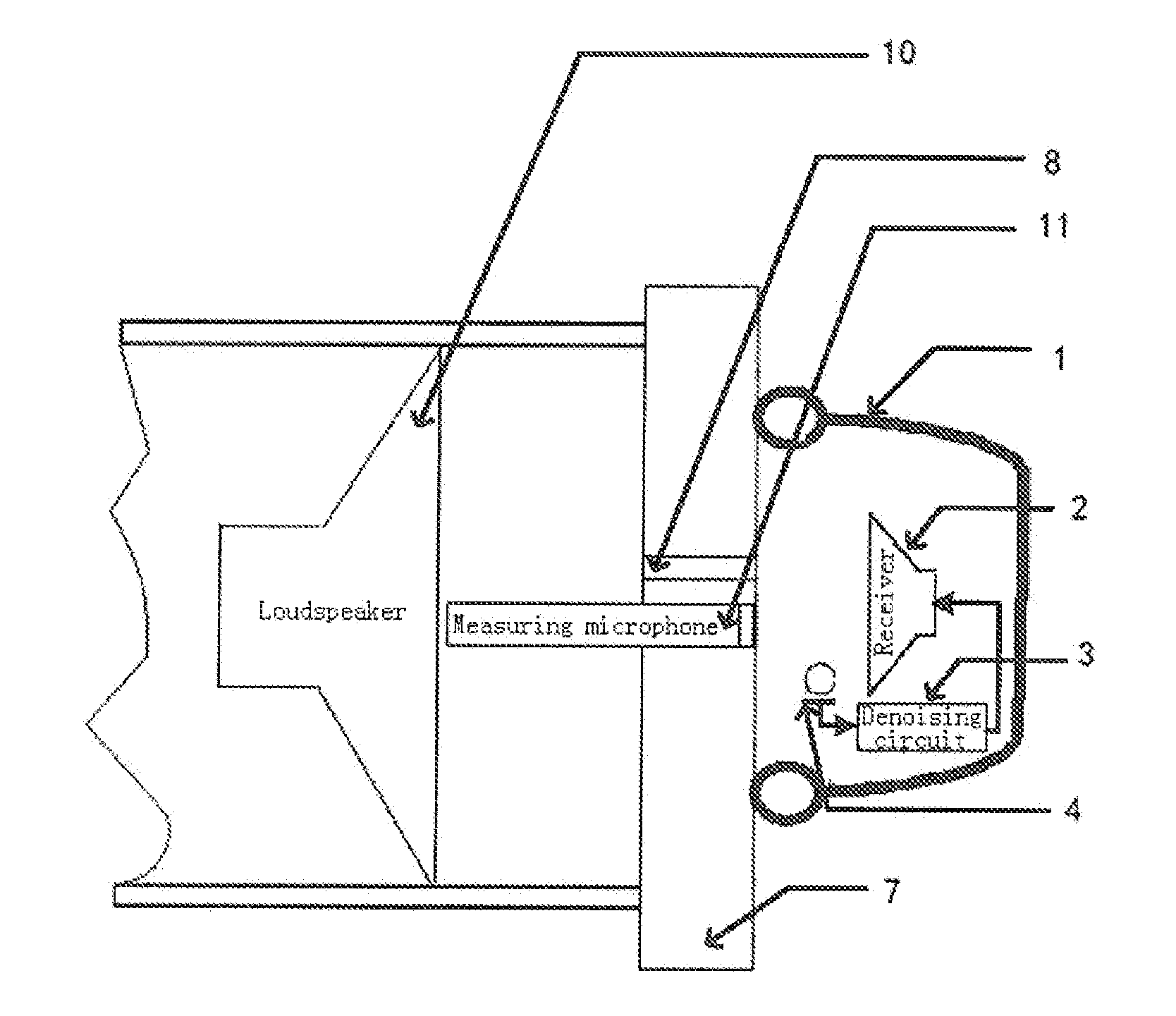
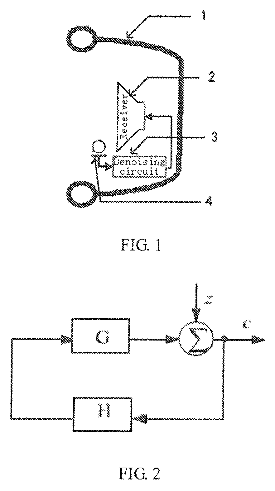
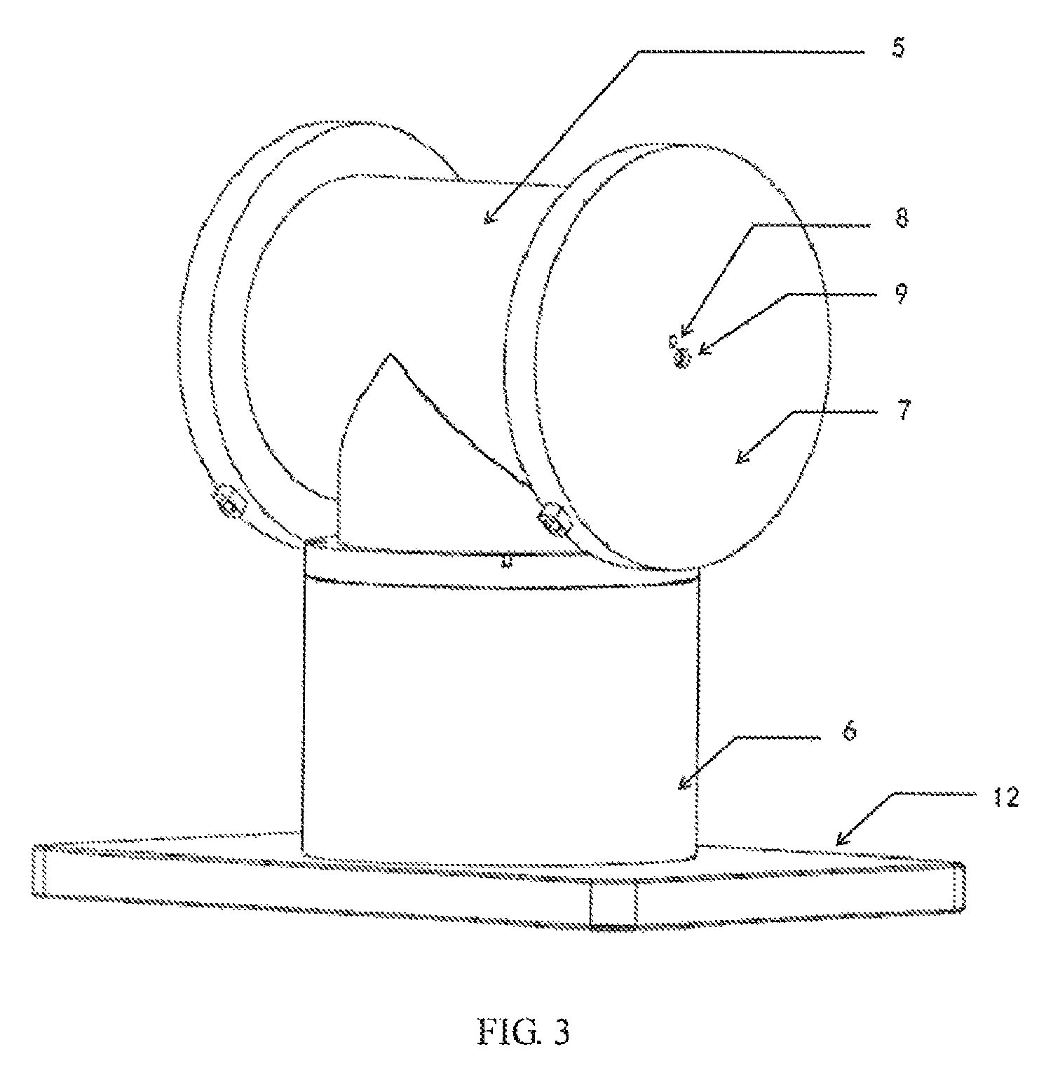
[0031]FIG. 3 is a schematic view of the external structure of the test device for the noise reduction headphone according to embodiment 1 of the present invention. FIG. 4 is a schematic view showing the internal structure of the test device for the noise reduction headphone show in FIG. 3 and the test in cooperation with the headphone.

[0032]Referring to FIG. 3 and FIG. 4, the test device according to this embodiment is a test device suitable for a circumaural noise reduction headphone, comprising: an enclosed cavity consisting of a base 12, a vertical cavity 6, a horizontal cavity 5 and a test panel 7. In this embodiment a loudspeaker 10 is taken as the noise source, and in other embodiments of the present invention a simulation mouth or other sound source components can be used instead.

[0033]The lower end of the vertical cavity 6 is fixed on the base 12, the upper end of the vertical cavity 6 is communicated with the horizontal cavity 5; the two ends of the horizontal cavity 5 are ...

embodiment 2

[0042]FIG. 5 is a schematic view showing the structure of the noise reduction headphone and its test device according to embodiment 2 of the present invention. Referring to FIG. 5, it shows a measuring microphone 51, a receiver 52 of the circumaural noise reduction headphone, a noise reduction microphone 53 of the circumaural noise reduction headphone, a simulation mouth 54 as a noise source, a test panel 55 and a sound guiding hole 56.

[0043]The structure of the test device in embodiment 2 as shown in FIG. 5 is similar to the structure of the test device in embodiment 1 as shown in FIGS. 3 and 4, and both are test devices suitable for the circumaural noise reduction headphone. The difference lies in that in FIG. 5 the enclosed cavity consists of a cylindrical cavity and test panels placed at two ends of the cavity, and the noise source is a simulation mouth located outside of the enclosed cavity. The simulation mouth is connected with an interface on the enclosed cavity, such that t...

embodiment 3

[0045]FIG. 6 is a schematic view showing the structure of the noise reduction headphone and its test device according to embodiment 3 of the present invention. Referring to FIG. 6, it shows a measuring microphone 62, a sound guiding hole 63, a loudspeaker 64, a test panel 65, a noise reduction microphone 66 of the noise reduction headphone and a receiver 67 of the noise reduction headphone. The test device according to this embodiment is applicable for the in-ear noise reduction headphone.

[0046]Referring to FIG. 6, in embodiment 3, the noise source is located within the enclosed cavity. The test panel is a concave which simulates the auricle of human ear. In the test, the test panel cooperates with the in-ear noise reduction headphone to form a coupling cavity 61. In FIG. 6, the notch of the test panel is directed towards the horizontal direction. In other embodiments of the present invention, the notch of the test panel may also face upwards.


PUM


Abstract

The present invention discloses a test device and test method for the noise reduction headphone. The test device comprises: an enclosed cavity, a noise source, a test panel, a measuring microphone and a measure comparison module connected with the measuring microphone. The sound emitted from the noise source is sealed within the enclosed cavity. The test panel can cooperate with the noise reduction headphone to form a coupling cavity in the test. The test panel has a sound guiding hole in the common part with the enclosed cavity for transmitting the sound of the noise source into the interior of the coupling cavity. The test panel also has a mounting hole, and the measuring microphone is mounted on the mourning hole towards the direction of the coupling cavity. The measuring microphone records noise signals before and after the noise reduction function of the noise reduction headphone is activated. The measure comparison module receives the signals recorded these two times by the measuring microphone and performs comparison processing to obtain noise reduction amount of the noise reduction headphone. The technical solution of the present invention solves the problem of noise pollution caused by high-power external noise sources to the surrounding environment during the test process of noise reduction amount of the headphone, meanwhile, no special shielding room is required, and the requirement on test environment is relieved.

Description

TECHNICAL FIELD[0001]The present invention relates to the technical field of headphone production and test, and particularly relates to a test device and test method for a noise reduction headphone.BACKGROUND OF THE INVENTION[0002]In high noise environment, in order to protect audition and perform normal communication, the noise reduction headphone is widely used.[0003]During the process of development and production of active noise reduction headphones, the noise reduction amount of the headphone must be tested to determine whether the headphone is qualified. The main work frequency band of the feedback active noise reduction headphone is generally in the range of 20 Hz-4 kHz. In the currently known test solutions, the headphone is worn on a simulation human head or a similar device, and a set of external noise sources are used to generate noise with enough large sound pressure level and enough low frequency at a certain distance. The noise reduction switch of the headphone is swit...

Claims


Application Information

Patent Timeline
Patent Type & Authority Patents(United States)
IPC IPC(8): H04R29/00H04R1/10
CPCH04R29/001H04R1/1083H04R29/00
Inventor LIU, SONGZHAO, JIANHUA, YANG
Owner GOERTEK INC
Why Eureka
Try Eureka