Buck-boost converter with buck-boost transition switching control

a converter and control technology, applied in the direction of dc-dc conversion, power conversion systems, instruments, etc., can solve the problems of slow response, large lq (quiescent or ground current), and lower efficiency at the transition region

Active Publication Date: 2015-07-21
TEXAS INSTR INC
View PDF17 Cites 29 Cited by
  • Summary
  • Abstract
  • Description
  • Claims
  • Application Information

AI Technical Summary

Benefits of technology

[0020]In another embodiment, the buck-boost regulation methodology can be adapted for a single-inductor buck-boost converter configured with a four transistor switching network, where the switching controller includes: (a) zero crossing comparators ZCC3 and ZCC4 configured to provide respective zero crossing signals ZC3 and ZC4, and to control switching of respectively S3 and S4; (b) a state machine configured to control switching of S1 and S2 based on the zero crossing signals ZC3 and ZC4, and an IL regulation error signal; and (c) IL regulation circuitry configured to provide the IL regulation error signal based on (i) an IL sense signal representative of the inductor current IL, and (ii) a voltage regulation error signal representative of a difference between an output voltage supplied to the load (based on IL), and the regulated output voltage; such that (d) the switching converter supplies inductor current IL corresponding to the regulated output voltage. For this embodiment, the switching controller can include: (a) IL sense circuitry configured to provide an IL sense current representative of the inductor current IL; (b) VOUT sense circuitry including (i) a reference voltage corresponding to the regulated output voltage; and (ii) a transconductance amplifier configured to output a voltage regulation error current corresponding to a difference between an output voltage supplied to the load (based on IL), and the reference voltage; and (c) IL regulation circuitry that includes (i) a current subtraction node coupled to the output of the transconductance amplifier and the IL sense circuitry, such that a resulting IL regulation current out of the current subtraction node corresponds to a difference between the voltage regulation error current and the IL sense current; and (ii) an error comparator configured to provide the IL regulation error signal based on the IL regulation current relative to a comparator reference. For this embodiment, the comparator reference can corresponds to a predetermined hysteresis level.

Problems solved by technology

Disadvantages of this approach include lower efficiency at the transition region due to excessive commutations, and larger lq (quiescent or ground current resulting from DC biasing, i.e., current not available for the load).
Disadvantages of this approach include slow response due to “cycling”, and if the unregulated input voltage goes significantly below the regulated output voltage, significant circuit stability problems can result.
Disadvantages of this approach include slower response to rapid changes in load current, and unpredictable operation when the input and output voltage are nearly equal.
A disadvantage of this approach is clocking which requires high lq and lower efficiency at low load currents, as well as chaos effects and sub-harmonic oscillations.

Method used


Image

  • Buck-boost converter with buck-boost transition switching control
  • Buck-boost converter with buck-boost transition switching control
  • Buck-boost converter with buck-boost transition switching control

Examples


Embodiment Construction

[0027]This Description and the Figures disclose example embodiments and applications that illustrate various features and advantages of the invention, aspects of which are defined by the Claims. Known circuits, functions and operations are not described in detail to avoid unnecessarily obscuring the principles and features of the invention.

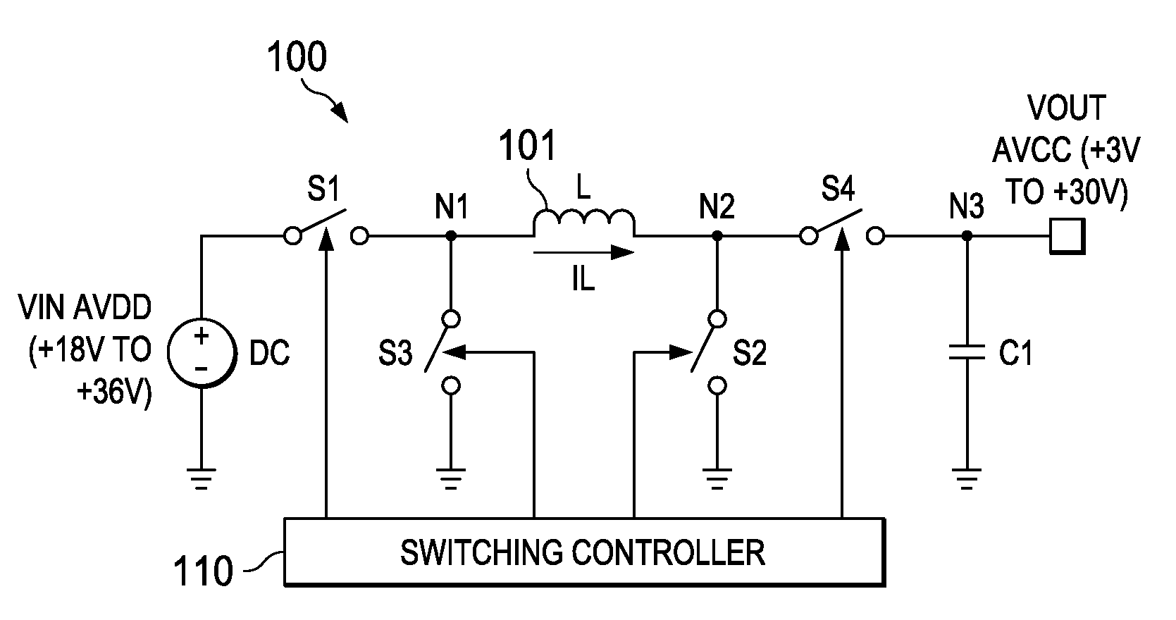
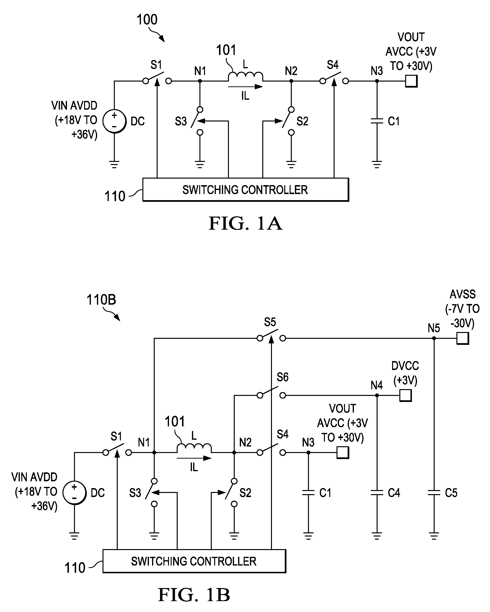
[0028]The buck-boost regulation (switching control) methodology, including buck-boost transition switching control, according to the invention, can be adapted for single inductor buck-boost switching converter / regulator architectures operating in DCM (discontinuous conduction mode). Converter and regulator can be used interchangeably, although, in general, a regulator includes converter circuitry together with an appropriate inductor and output capacitor (i.e., for typical applications, the inductor and output capacitor will not be integrated with the converter circuitry). The converter circuitry includes a switching network coupled to the inducto...


PUM


Abstract

A buck-boost regulation methodology operable, in one embodiment, with a single inductor, four-switch (S1-S4) buck-boost regulator configured for DCM. Buck-boost transition switching control is operable when inductor charge time exceeds a max charge time, and inductor discharge time exceeds a max discharge time, and includes: (a) during charge transition cycles, at the end of the max charge time, if IL is less than a predetermined peak current IL<sub2>—< / sub2>MAX, switching S2 on (grounding the output side of the inductor) and S4 off, causing IL to increase (a rapid S1S2 charging current ramp), until IL reaches IL<sub2>—< / sub2>MAX, and (b) during discharge transition cycles, at the end of the max charge time, if IL is greater than zero, switching S1 off and S3 on (grounding the input side of the inductor), causing IL to increase (a rapid S3S4 IL discharging current ramp), until IL reaches zero.

Description

CROSS-REFERENCE TO RELATED APPLICATIONS[0001]Priority is hereby claimed under USC §119(e) to U.S. Provisional Application 61 / 883,651 and 61 / 764,904.BACKGROUND[0002]1. Technical Field[0003]This Patent Disclosure relates generally to buck-boost switching converters / regulators, and more particularly to implementing switching control during buck-boost transitions.[0004]2. Related Art[0005]Buck-boost switching converter topologies typically require some switching control mechanism to ensure correct operation during transitions between buck and boost, where input and output voltages are close together and load currents are low.[0006]One common approach is dual ramp PWM (pulse width modulation). Disadvantages of this approach include lower efficiency at the transition region due to excessive commutations, and larger lq (quiescent or ground current resulting from DC biasing, i.e., current not available for the load).[0007]Another common approach is using a comparator to determine whether th...

Claims


Application Information

Patent Timeline
Patent Type & Authority Patents(United States)
IPC IPC(8): G05F1/00H02M3/158
CPCH02M3/1582
Inventor IVANOV, VADIM V.PRAKASH, RAHUL
Owner TEXAS INSTR INC
Why Eureka
Try Eureka