
Propulsion system for multihull watercraft

a technology for watercraft and propulsion systems, applied in marine propulsion, vessel construction, energy supply, etc., can solve the problems of tripping hazards, insufficient floatation and height above the waterline at this location to protect the propulsion unit, and large drag on a displacement hull

Inactive Publication Date: 2015-07-28
CASPERSON JOHN R
View PDF15 Cites 11 Cited by
  • Summary
  • Abstract
  • Description
  • Claims
  • Application Information

AI Technical Summary

Benefits of technology

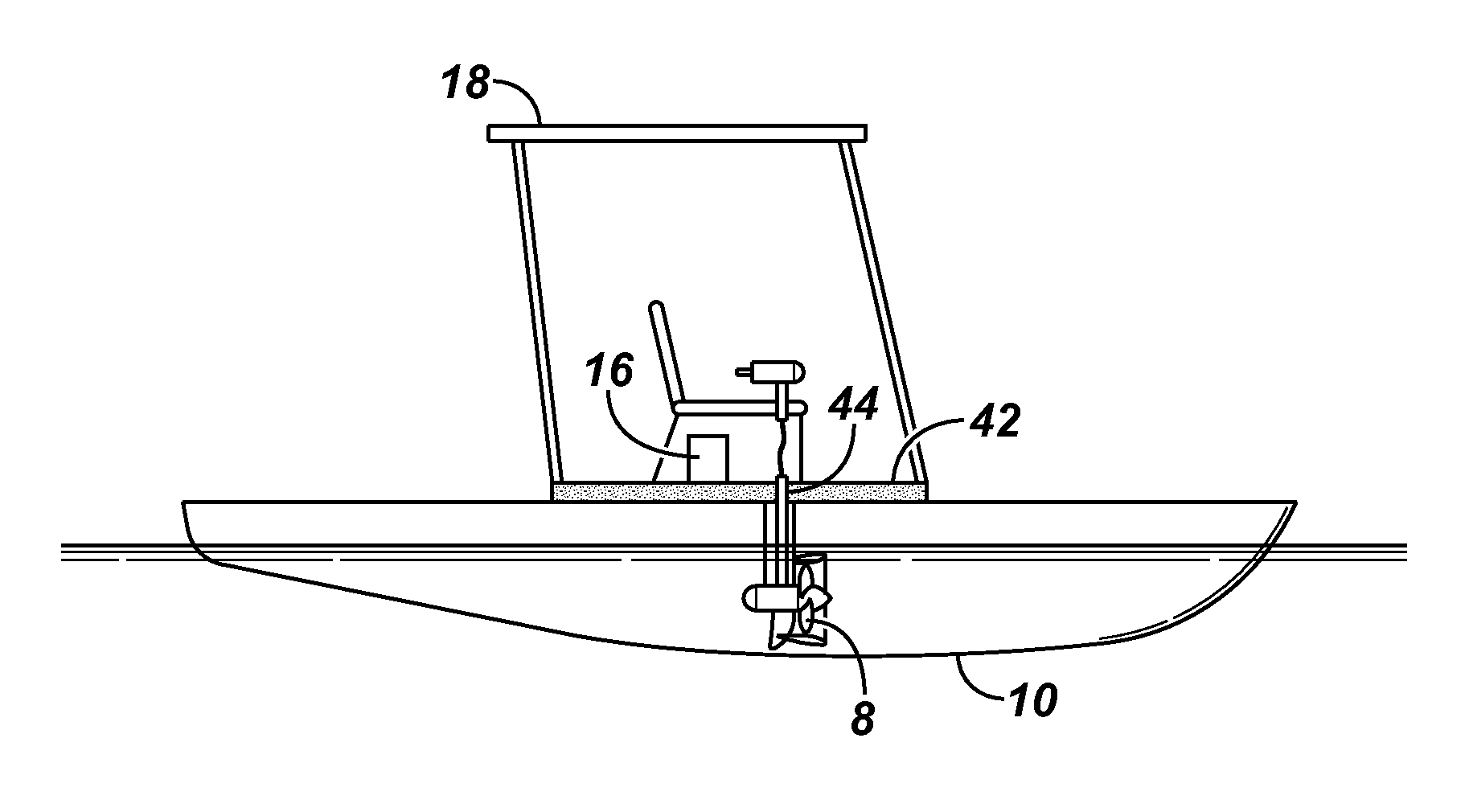
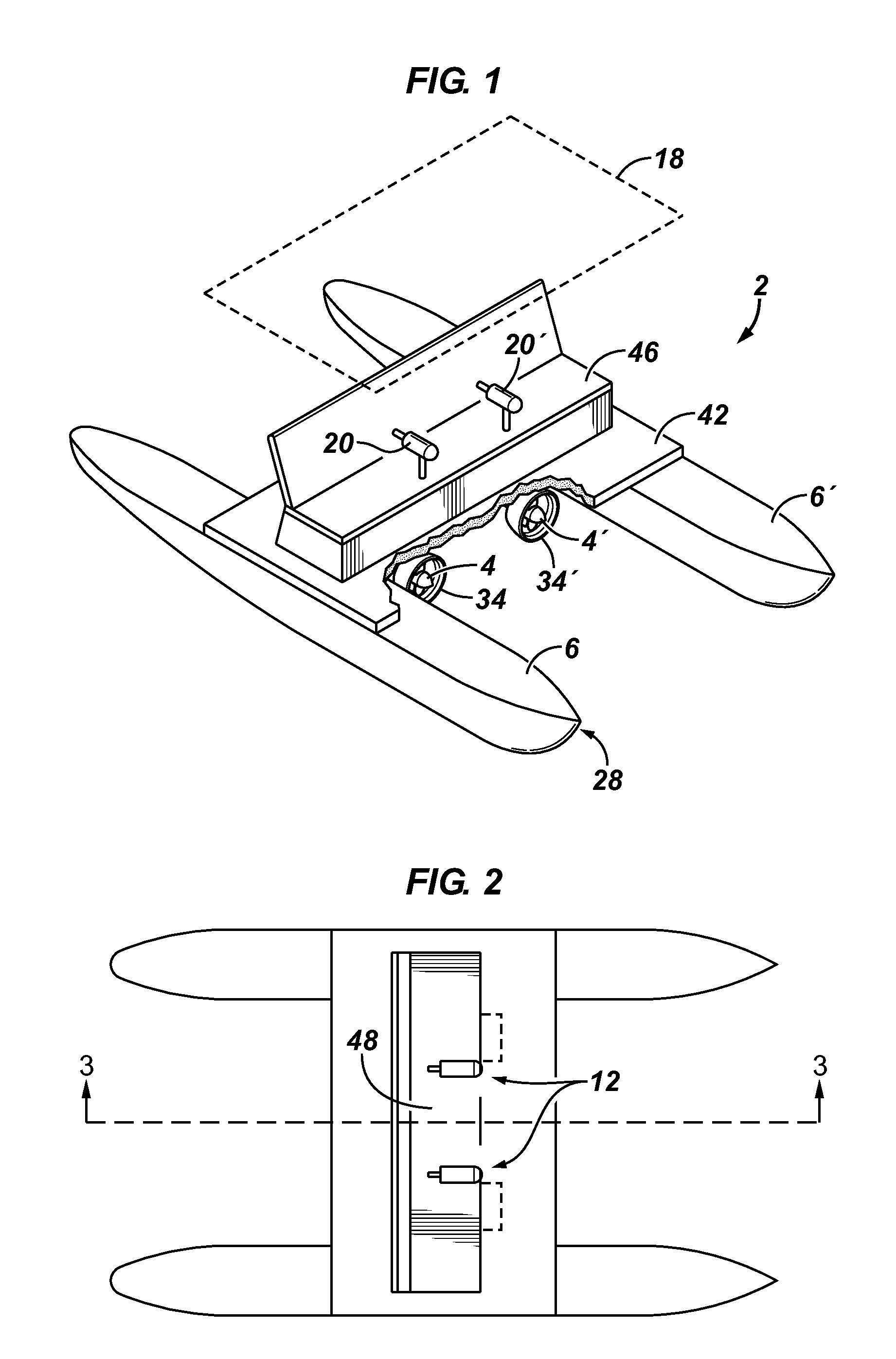
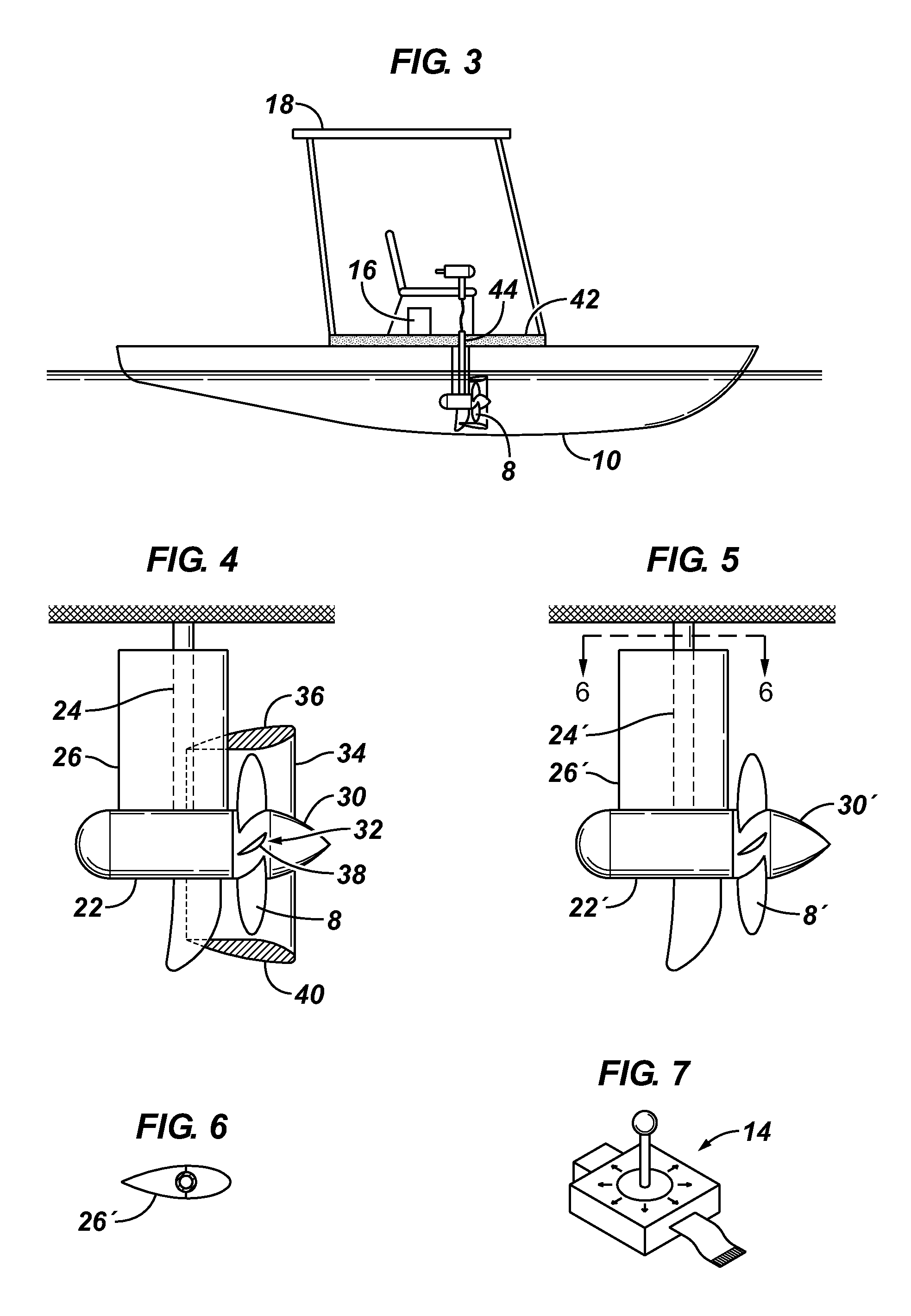
The invention is a multihull watercraft with electric trolling motors positioned in the center of the watercraft. The motors have propellers that engage the water within the middle of the watercraft and draft less than the outermost hulls. The motors have fairings to reduce drag. Another embodiment has a propeller shroud mounted on the trolling motor to improve thrust. The motor casing is positioned at a right angle to the downshaft and the propeller shaft extends axially from the motor. The blades of the propeller have an airfoil-shaped cross-section. These technical effects provide improved efficiency and control for the watercraft.

Problems solved by technology

For lightweight hulls, such as those employed in beach catamarans, however, there is inadequate floatation and height above the waterline at this location to protect the propulsion unit from splashing or immersion, particularly if the operator is near the back of the boat.
Additionally, excess weight at the back of the boat tends to immerse the transoms when underway, which produces much drag for a displacement hull.
An additional consideration with stern mounted propulsion units is the provision of the steering mechanism, which presents a tripping hazard and attack point for corrosion, power sources, such as batteries or fuel tanks, which affect the trim of the vessel and present a tripping hazard, and lines such as fuel lines and / or battery cables, running from the power sources to the propulsion units, which present a tripping hazard, and in the case of battery cables, waste energy.

Method used


Image

  • Propulsion system for multihull watercraft
  • Propulsion system for multihull watercraft
  • Propulsion system for multihull watercraft

Examples


Embodiment Construction

[0021]A catamaran or trimaran can be skid-steered by two widely spaced propulsion units positioned amidships, inboard of the outermost hulls. The only controls necessary are those which provide the ability to control propulsion unit speed and the direction of propeller rotation. The propulsion units are positioned to provide thrust parallel to the boat axis, and are preferably fixed in such position. Because the need to control motor tilt and direction is eliminated, the conventional trolling motor mounting brackets can be totally eliminated and the downshafts secured to the deck or hatches in the deck by collars or the like to save weight.

[0022]The amidships position of the propulsion units facilitates “skid steering” the boat, particularly in a cross wind, as compared to stern mounted units. The ability to turn the propulsion units is not needed, nor is a rudder nor the means for controlling it. However, in the embodiment of the invention shown in FIG. 8, a rudder may be needed, a...


PUM


Abstract

One embodiment of the invention provides a multihull watercraft having outermost hulls, a length, and a pair of propulsion units positioned inboard of its outermost hulls in a central ½ of the watercraft length. The propulsion units include propellers which are positioned to engage the water within the central ½ of the watercraft length and draft less than the outermost hulls. Because the outermost hulls provide protection from obstacles, the propulsion units can be operated propeller-end first, at a sufficiently high efficiency so that solar power for electric motors becomes an economically viable power source.

Description

FIELD OF THE INVENTION[0001]This invention relates to a propulsion system for watercraft, and is expected to be especially useful for multihull vessels having displacement hulls.BACKGROUND OF THE INVENTION[0002]Efforts have been made to position propulsion units at the sterns of multihull vessels, such as catamarans and trimarans.[0003]For lightweight hulls, such as those employed in beach catamarans, however, there is inadequate floatation and height above the waterline at this location to protect the propulsion unit from splashing or immersion, particularly if the operator is near the back of the boat. Additionally, excess weight at the back of the boat tends to immerse the transoms when underway, which produces much drag for a displacement hull. A technique for protecting the propulsion units from water would be desirable, as well as a technique powering a lightweight powered catamaran that makes headway without immersing the transoms.[0004]A further consideration relating to pos...

Claims


Application Information

Patent Timeline
IPC IPC(8): B63B1/00B63H20/02H02J7/00B63B17/00B63H21/17B63H5/08
CPCB63H5/08B63B17/00B63H20/02B63H21/17H02J7/00B63B2209/18B63H20/007B63H25/42B63H2005/1258B63H2021/171B63H2025/026Y02T70/5236
Inventor CASPERSON, JOHN R
Owner CASPERSON JOHN R
Learn More