Supercharge Your Innovation With Domain-Expert AI Agents!

Label edge detection using out-of-plane reflection

Active Publication Date: 2015-07-28
LYONS GREGORY JON
View PDF18 Cites 0 Cited by
  • Summary
  • Abstract
  • Description
  • Claims
  • Application Information

AI Technical Summary

Benefits of technology

The patent describes a label sensor that can detect different types of labels without needing manual adjustments. This is because the sensor can determine which type of label it is detecting based on the sequence of light reflections.

Problems solved by technology

But the way die-cut and butt-cut labels are currently made results in their edges having an angularity or curvature to them when viewed in cross section.

Method used


Image

  • Label edge detection using out-of-plane reflection
  • Label edge detection using out-of-plane reflection
  • Label edge detection using out-of-plane reflection

Examples


first embodiment

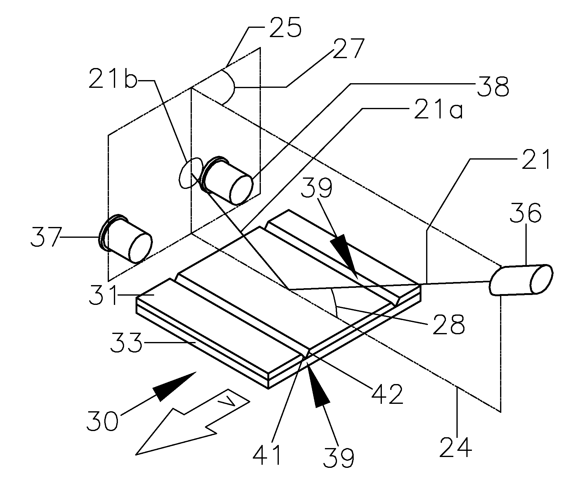
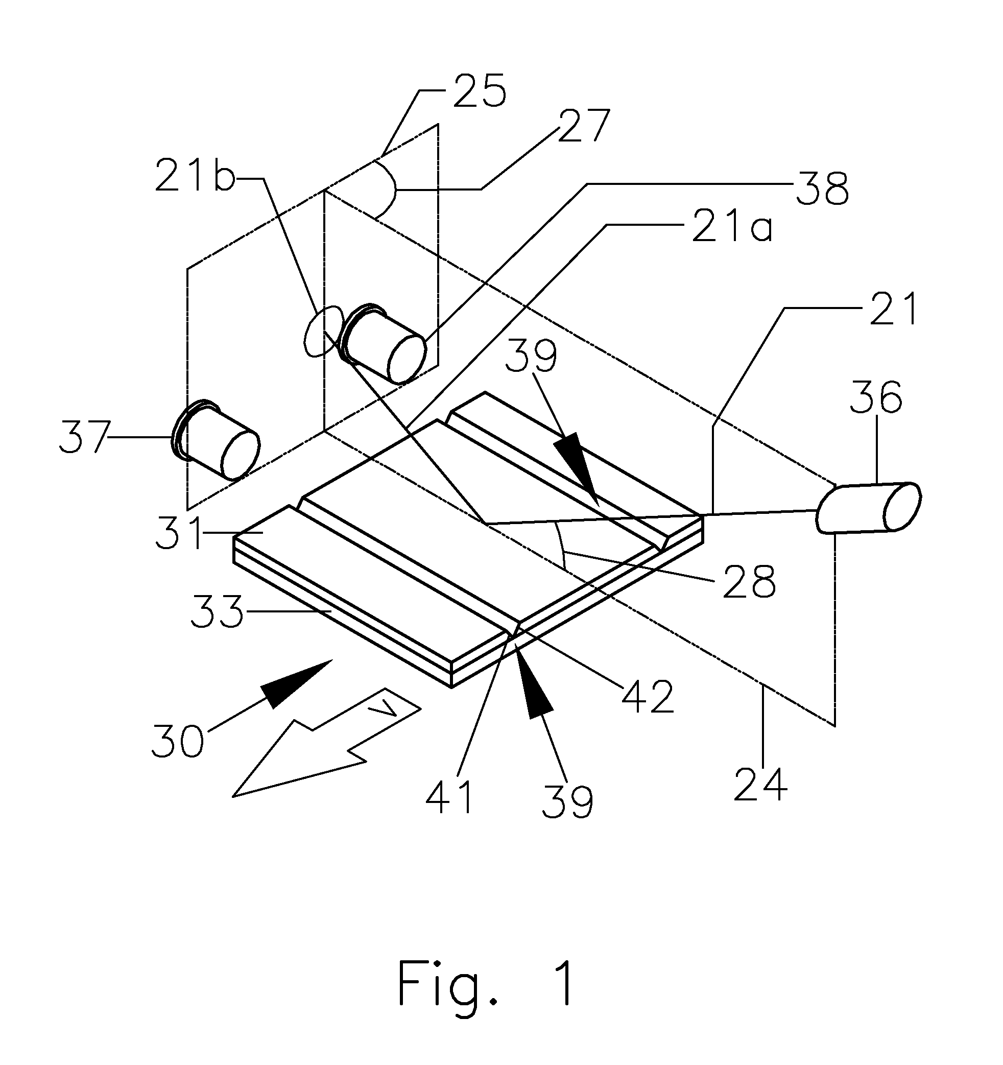
[0089]FIG. 3 shows parts of the first embodiment of a sensor designed to use out-of-plane reflection of light off label edges to detect the location of die-cut labels.

[0090]In FIG. 3 there is a light source 36 that emits a small beam of light whose direction is represented schematically in this disclosure by an incident ray 21. Hereafter in this disclosure, the entire beam of light will be referenced as incident ray 21. Light source 36 may include some parts not shown, including (for example) a light-emitting or laser diode and whatever optical components are required to shape the light from that diode into a small light beam. Those parts are not shown, because the use of light-emitting and laser diodes, lenses, fiber optic cables, light guides, apertures, windows, etc. to produce light beams is well-known to those experienced in the art.

[0091]Experimentation has shown that if incident ray 21 is about 0.5 mm (0.02 inch) in diameter, it will work with label material that is 0.069 mm ...

second embodiment

[0114]FIGS. 6 and 7 show a possible alternative embodiment of the label sensing method, the only structural difference being that angle 27 is no longer 90°. The detection plane is still parallel to the direction of motion of web 30.

[0115]In the first embodiment, the light pattern formed in detection plane 25 by the various light beams that are reflected off flat surfaces and edges tends to be generally symmetrical on both sides of initial incidence and reflection plane 24. But due to the asymmetry of this arrangement, light spots 22a and 23a will no longer be symmetrical.

[0116]This embodiment as shown in FIG. 7, with angle 27 greater than 90°, may be useful at some point. But it may enhance the detection of leading edge 42 at the cost of worse detection of trailing edge 41. As angle 27 gets increasingly larger than 90°, trailing edge 41 will tend to be more and more in a shadow, and could at some value of angle 27 become undetectable if incidence angle 28 is sufficiently small. This...

third embodiment

[0118]FIG. 8 illustrates a third embodiment that's simplified from the preceding examples. It shows the label-edge position at which leading edge 42 is detected. It uses only photodetector 37 instead of two photodetectors. This still enables the sensor to detect the leading label edges 42 of both butt-cut and die-cut labels. If one wanted to detect trailing label edges 41 instead, then photodetector 37 would be omitted and photodetector 38 would be used instead, and it would be positioned as shown in FIGS. 1-7. This embodiment would still detect the edges of both die-cut and butt-cut labels, but it wouldn't know which of the two kinds of labels it was sensing, and would be unable to tell which direction web 30 was moving.


PUM


Abstract

This disclosure describes an optical method of detecting the presence of pressure-sensitive labels, using the reflective properties of their edges. Labels that are removably attached to a liner are moved through a light beam that is directed across their direction of motion so the light impinges on the labels at a predetermined angle of incidence. The light remains in its initial incidence and reflection plane when it reflects off all parts of the liner and labels except the labels' edges. Due to the angularity of the labels' edges, the light beam is deflected out of the plane of incidence upon reflection off the edges, thus enabling detection of the label edges by light reflected out of the plane of incidence.

Description

CROSS-REFERENCE TO RELATED APPLICATIONS[0001]This application is a continuation-in-part of application Ser. No. 13 / 854,918 that was filed on 2013 Apr. 1 by the present inventor, which is incorporated by reference.STATEMENT REGARDING FEDERALLY SPONSORED RESEARCH OR DEVELOPMENT[0002]Not Applicable.THE NAMES OF THE PARTIES TO A JOINT RESEARCH AGREEMENT[0003]Not Applicable.INCORPORATION-BY-REFERENCE OF MATERIAL SUBMITTED ON A COMPACT DISC[0004]Not Applicable.BACKGROUND OF THE INVENTION[0005]1. Field of the Invention[0006]The present invention relates to a device for determining the position of the leading or training edge of a label that is on a continuous sheet, or web, of labels. The method and devices described herein relate to any operation where it's necessary or beneficial to detect either the simple presence or the exact position of a pressure-sensitive label. Examples of such operations can occur during the manufacture of the labels, when the labels are being applied to objects ...

Claims


Application Information

Patent Timeline
IPC IPC(8): G01B11/14
CPCG01B11/14G01B11/028G01V8/12
Inventor LYONS, GREGORY JON
Owner LYONS GREGORY JON
Features
  • R&D
  • Intellectual Property
  • Life Sciences
  • Materials
  • Tech Scout
  • Unparalleled Data Quality
  • Higher Quality Content
  • 60% Fewer Hallucinations
Learn More