Multiphase drilling systems and methods

a multi-phase drilling and multi-phase technology, applied in the direction of directional drilling, rotary drilling, drilling holes/well accessories, etc., can solve the problems of increasing bhp, increasing downtime, and shortening the life of the bit,

Inactive Publication Date: 2015-08-04
SUNCOR ENERGY INC +1
View PDF14 Cites 2 Cited by
  • Summary
  • Abstract
  • Description
  • Claims
  • Application Information

AI Technical Summary

Problems solved by technology

Deploying a drilling rig to a wellsite is an expensive task.
An increase in BHP also increases downtime by shortening the life of the bit, thereby requiring more frequent replacement or tripping of the drill bit.
However, air drilling is limited to select geological formations, which are consolidated with minimal water influx and do not produce hydrogen sulfide.

Method used


Image

  • Multiphase drilling systems and methods
  • Multiphase drilling systems and methods
  • Multiphase drilling systems and methods

Examples


Embodiment Construction

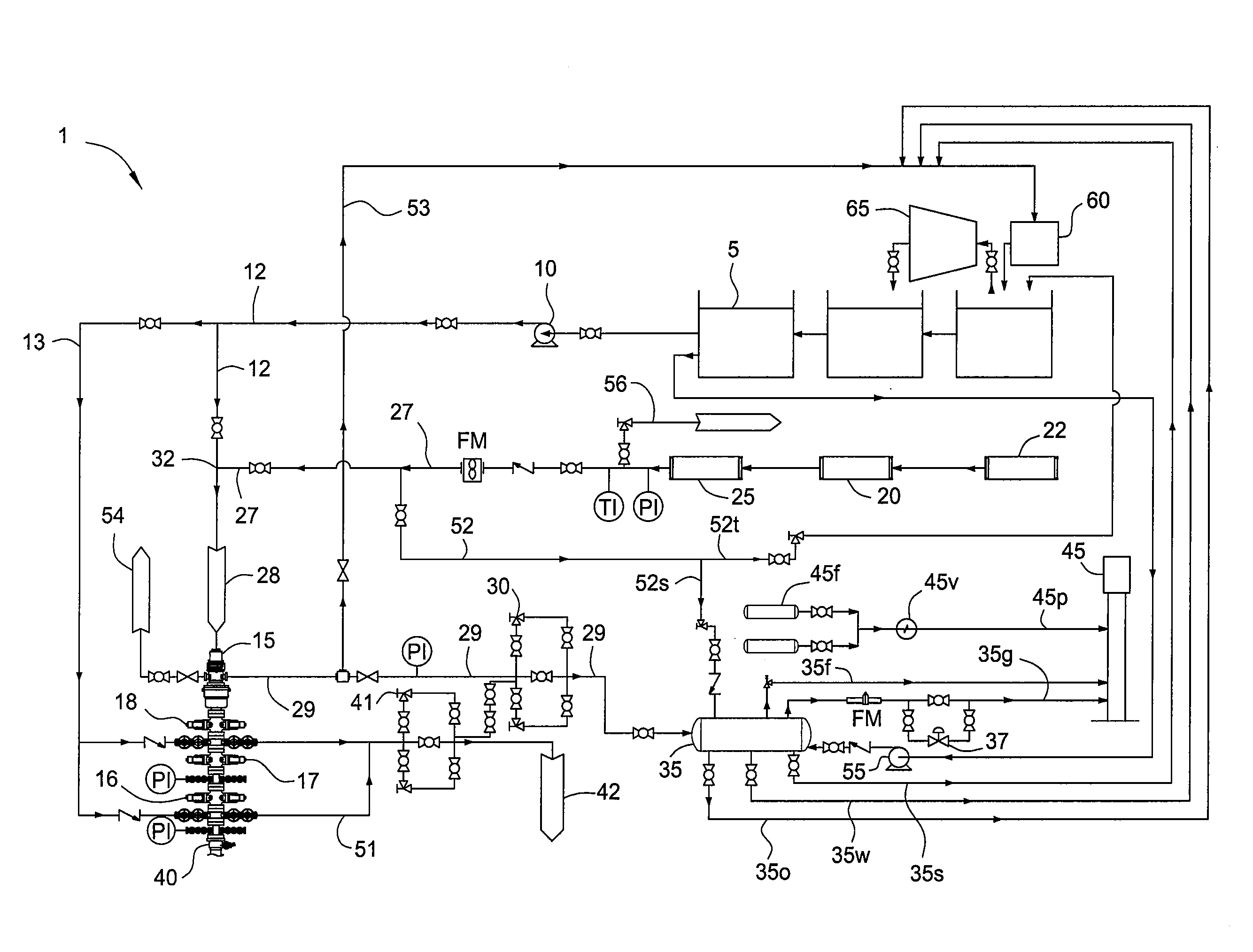
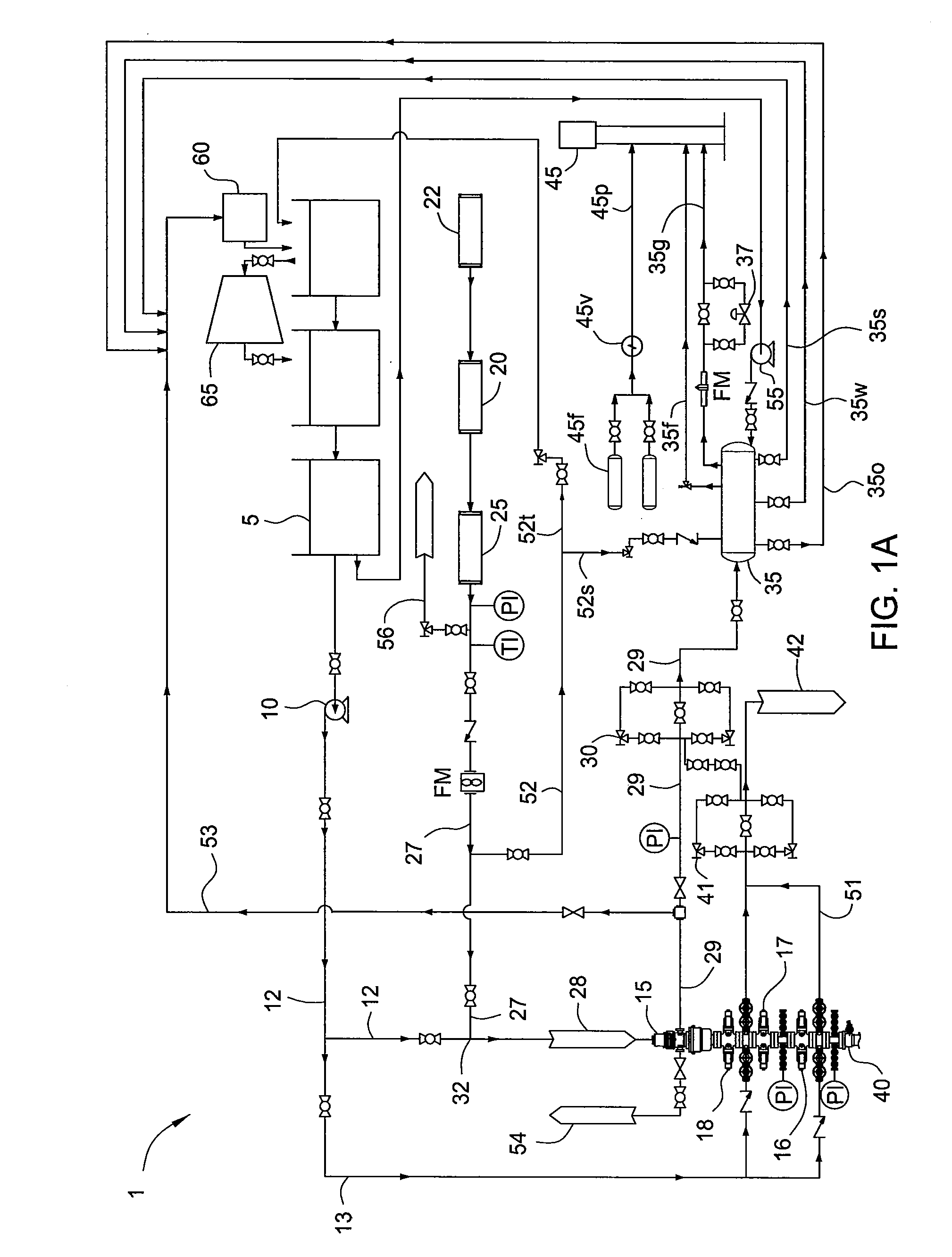
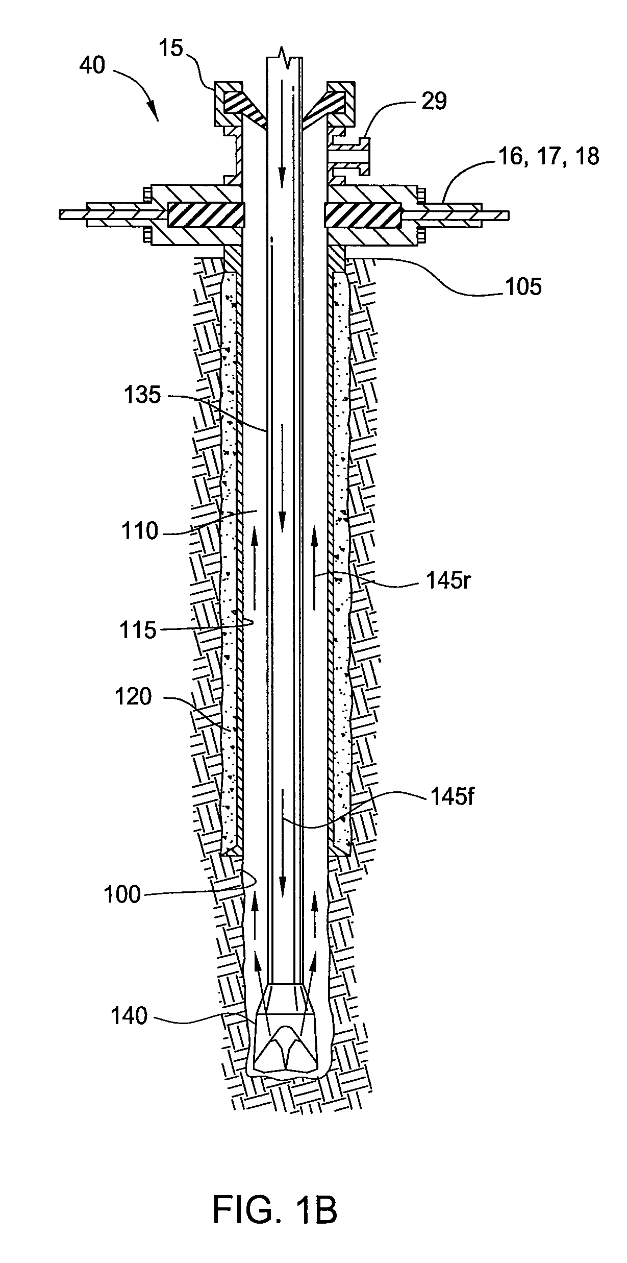
[0019]FIG. 1A is a flow diagram of a drilling system 1, according to one embodiment of the present invention. FIG. 1B is a cross-section of a wellbore 100 being drilled using the drilling system 1. The drilling system 1 may be deployed on land or offshore. The drilling system 1 may include a drilling rig (not shown) used to support drilling operations. The drilling rig may include a derrick supported from a support structure having a rig floor or platform on which drilling operators may work. Many of the components used on the rig, such as a Kelly and rotary table or top drive, power tongs, slips, draw works and other equipment, are not shown for ease of depiction. A wellbore 100 has already been partially drilled, casing 115 set and cemented 120 into place. The casing string 115 extends from the surface 105 of the wellbore 100 where a wellhead 40 is typically located. Drilling fluid 145f may be injected through a drill string 135 deployed in the wellbore.

[0020]The drilling fluid 14...


PUM


Abstract

In one embodiment, a method for drilling a wellbore includes injecting drilling fluid through a drill string disposed in the wellbore and rotating a drill bit disposed on a bottom of the drill string. The drilling fluid includes a liquid and a gas. The drilling fluid is injected at the surface. The drilling fluid exits the drill bit and carries cuttings from the drill bit. The drilling fluid and cuttings (returns) flow to the surface via an annulus formed between the drill string and the wellbore. The liquid is injected at a rate so that a liquid velocity of the returns in the annulus is sufficient to transport the cuttings. The method further includes drilling through at least a portion of a non-productive formation.

Description

CROSS-REFERENCE TO RELATED APPLICATIONS[0001]This application claims benefit of U.S. Prov. Pat. App. No. 61 / 159,176, filed Mar. 11, 2009, and U.S. Prov. Pat. App. No. 61 / 089,456, filed Aug. 15, 2008, both of which are herein incorporated by reference in their entireties.BACKGROUND OF THE INVENTION[0002]1. Field of the Invention[0003]The present invention relates to multiphase drilling systems and methods.[0004]2. Description of the Related Art[0005]Drilling a wellbore typically requires circulating a drilling fluid to flush the bore of cuttings produced by action of a rotating drill bit. The drilling fluid may be pumped down the well inside the drill string and through the bit and jetted into the cutting face where it assists in penetrating the fractures created by the bit, lifting the bit fractured chips by penetrating the fractures and hydraulically lifting the chips into the circulating fluid stream. The drilling fluid then carries the chips up the lower annulus formed between an...

Claims


Application Information

Patent Timeline
Patent Type & Authority Patents(United States)
IPC IPC(8): E21B21/14E21B21/08
CPCE21B21/08E21B21/14C09K8/38E21B3/04E21B4/02E21B7/00E21B21/067E21B21/16
Inventor POMERLEAU, DANIEL GUYCORB, KEITH KENNETHBUTLER, STUART DWIGHTSTAYSKO, ROBERT T.JOLLYMORE, GREGG MACKAY
Owner SUNCOR ENERGY INC
Why Eureka
Try Eureka