Method for estimating and controlling driveline torque in a continuously variable hydro-mechanical transmission

a technology of hydro-mechanical transmission and driveline torque, which is applied in the direction of analogue processes, instruments, and specific applications, can solve the problems of potentially damaging high level of driveline torque, and achieve the effects of reducing torque, reducing engine speed, and reducing movement speed

Active Publication Date: 2015-08-04
BLUE LEAF I P INC
View PDF27 Cites 16 Cited by
  • Summary
  • Abstract
  • Description
  • Claims
  • Application Information

AI Technical Summary

Benefits of technology

[0007]What is disclosed is a method of estimating driveline torque of a continuously variable hydro-mechanical transmission of a work machine, particularly in the final gear reduction or output member, and limiting the torque for preventing damage to the transmission, without the shortcomings set forth above.
[0011]According to one aspect of the invention, it has been found that the pressure in the hydrostatic power unit will provide an indication of the torque on that unit, and if the operating mode, e.g., generation, regeneration, and the mechanical efficiency of the fluid motor and direction of operation thereof are known at the pressure, a relatively accurate estimation of the torque on the fluid motor can be made. In turn, the torque on the output of the planetary power unit can be estimated as a function of the torque on the fluid motor and ratios of gears of the planetary unit and those connecting it with the motor. The accuracy of this torque can be increased by knowing the efficiency of the planetary unit. The torque load on the driveline, particularly on the output member thereof, can then be estimated as a function of the estimated torque on the planetary unit output, and the ratio of gears connecting the planetary unit to the driveline output member.

Problems solved by technology

The driveline torque can reach a potentially damaging high level when the hydrostatic power unit is in the generation mode wherein the pump of that unit is functioning as a pump, and also when in the regeneration mode when the pump is being driven by the motor.

Method used


Image

  • Method for estimating and controlling driveline torque in a continuously variable hydro-mechanical transmission
  • Method for estimating and controlling driveline torque in a continuously variable hydro-mechanical transmission
  • Method for estimating and controlling driveline torque in a continuously variable hydro-mechanical transmission

Examples


Embodiment Construction

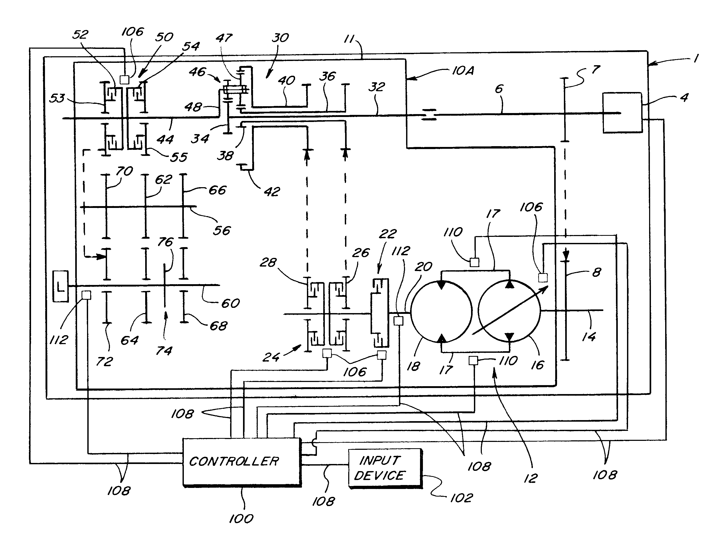
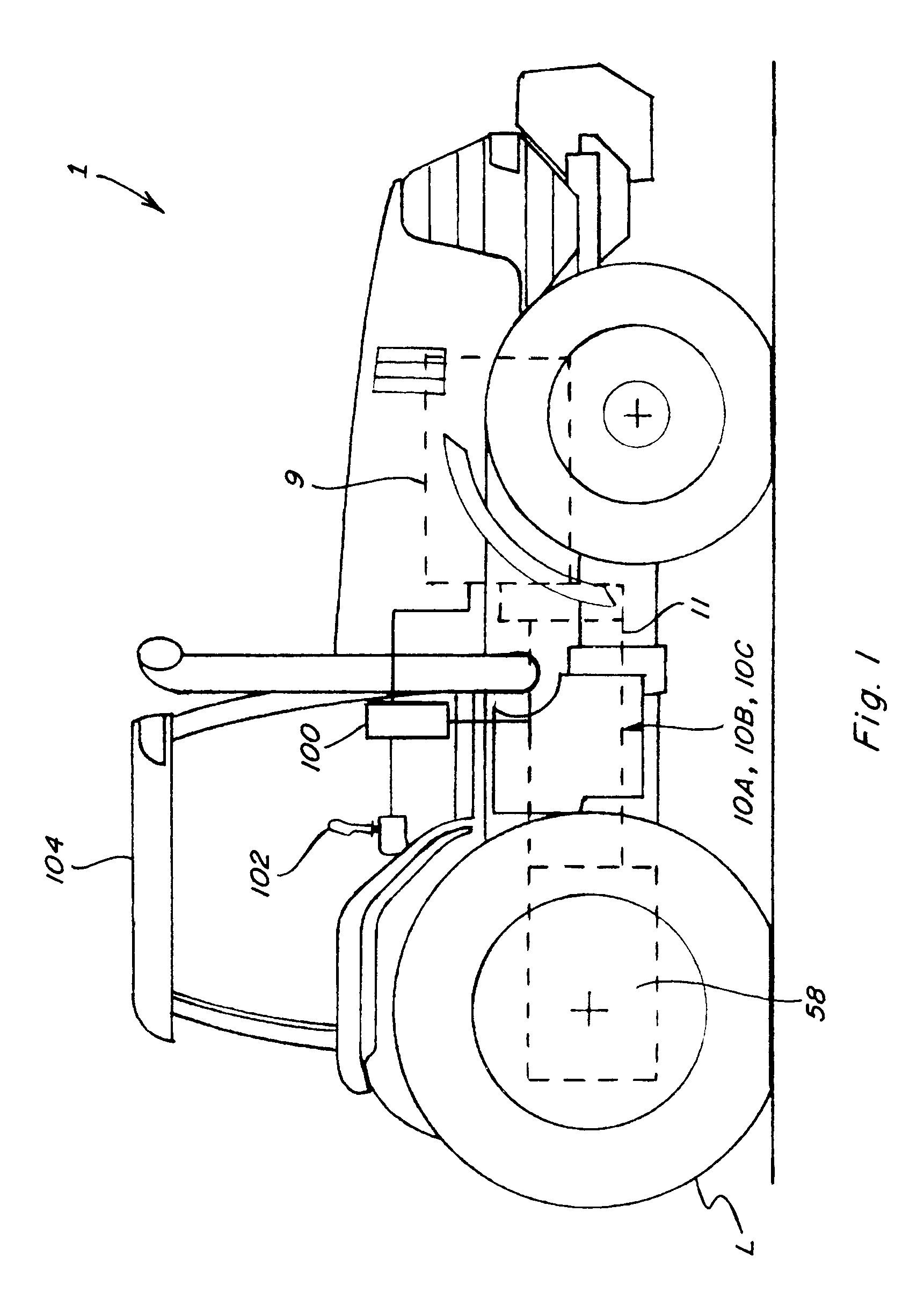
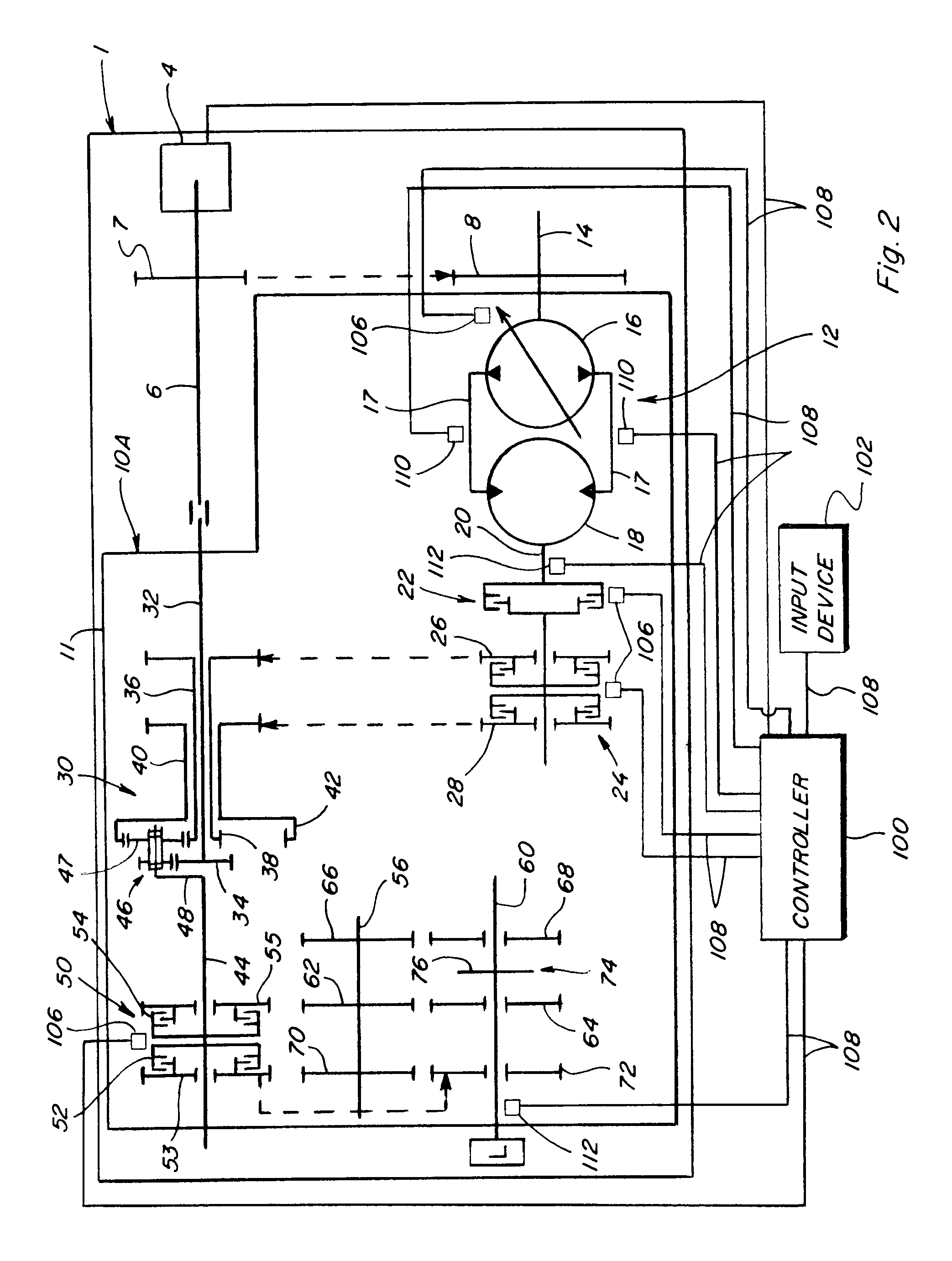
[0022]Referring now to the drawings, in FIG. 1 a work machine 1 is shown, which is a tractor representative of those that can be used for a variety of uses, including, but not limited to, agriculture, construction, earth moving and forestry. Work machine 1 includes a power source 4 which will be, for instance, an internal combustion engine, and is mechanically coupled to a continuously variable hydro-mechanical transmission, three representative variants or embodiments of which are represented by numbers 10A, 10B and 10C, like parts of which being identified by like numbers. Each of transmissions 10A, 10B and 10C is controllably operable according to the method of the invention, for estimating and limiting driveline torque of the transmission, and the transmissions shown are intended to be exemplary of a wide range of possible hydro-mechanical architectures wherein the power is split between paths and different ranges are used, with which the present invention can be used.

[0023]Refe...


PUM


Abstract

The method of estimating and controlling driveline torque in a continuously variable hydro-mechanical transmission uses pressure data and other metrics of a hydrostatic power unit of the transmission in lieu of actual driveline torque data. A mechanical efficiency of the transmission is determined as a function of whether the power unit is operating in a power generation or regeneration mode, and the torque output of the power unit is estimated from that and other hydrostatic parameters. This is used to estimate a torque output of a planetary power unit of the transmission, and the torque on an output member of the driveline is then estimated using that value, and appropriate corrective action taken.

Description

TECHNICAL FIELD[0001]The present invention relates generally to estimating and controlling driveline torque in a continuously variable hydro-mechanical transmission, and more particularly, to a method that does so using pressure data and other metrics of the hydrostatic unit, in lieu of actual driveline torque data.BACKGROUND ART[0002]Continuously variable hydro-mechanical transmissions are used in a variety of work machines, including for construction, earth moving, forestry, and agriculture. Reference in this regard, Weeramantry, U.S. Pat. No. 7,063,638 B2, issued Jun. 20, 2006, which discloses a representative continuously variable hydro-mechanical transmission. Typically, a continuously variable hydro-mechanical transmission will have a hydrostatic unit as one power input to a planetary gear set, and a mechanical connection to the engine of the machine as a second power input, with the output of the planetary connected via a clutch to one or more final gear reductions in connect...

Claims


Application Information

Patent Timeline
Patent Type & Authority Patents(United States)
IPC IPC(8): G06F19/00F16H61/472F16H59/70F16H37/08F16H47/04
CPCF16H61/472F16H47/04F16H59/70F16H2037/0886F16H2059/6861
Inventor DIX, PETER J.BULGRIEN, GARTH H.PRASSE, ROBERT C.WEERAMANTRY, CECIL A.GUO, HAIBO
Owner BLUE LEAF I P INC
Why Eureka
Try Eureka