
Acoustic wave device having an inorganic insulator and an organic insulator

a technology of inorganic insulators and acoustic waves, which is applied in the direction of signaling systems, instruments, electrical apparatus, etc., can solve the problems of loss or decay of insertion, declination of the reliability of the acoustic wave device, etc., and achieves high long-term reliability and preferable high-frequency characteristics.

Active Publication Date: 2015-08-04
SKYWORKS PANASONIC FILTER SOLUTIONS JAPAN
View PDF19 Cites 0 Cited by
  • Summary
  • Abstract
  • Description
  • Claims
  • Application Information

AI Technical Summary

Benefits of technology

[0012]The acoustic wave device has preferable high-frequency characteristics and high long-term reliability.

Problems solved by technology

This influence generates a parasitic factor, such as a parasitic capacitance or inductance, hence causing insertion loss or decay to decline the high-frequency filtering characteristics of the acoustic wave device 1.
In the conventional acoustic wave device 1, the loading of a voltage under such a high moisture condition for a long duration of time may damage the resin material of the insulators 6, 8, and 10, and hence, result in declination of the reliability of the acoustic wave device 1.

Method used


Image

  • Acoustic wave device having an inorganic insulator and an organic insulator
  • Acoustic wave device having an inorganic insulator and an organic insulator
  • Acoustic wave device having an inorganic insulator and an organic insulator

Examples


exemplary embodiment 1

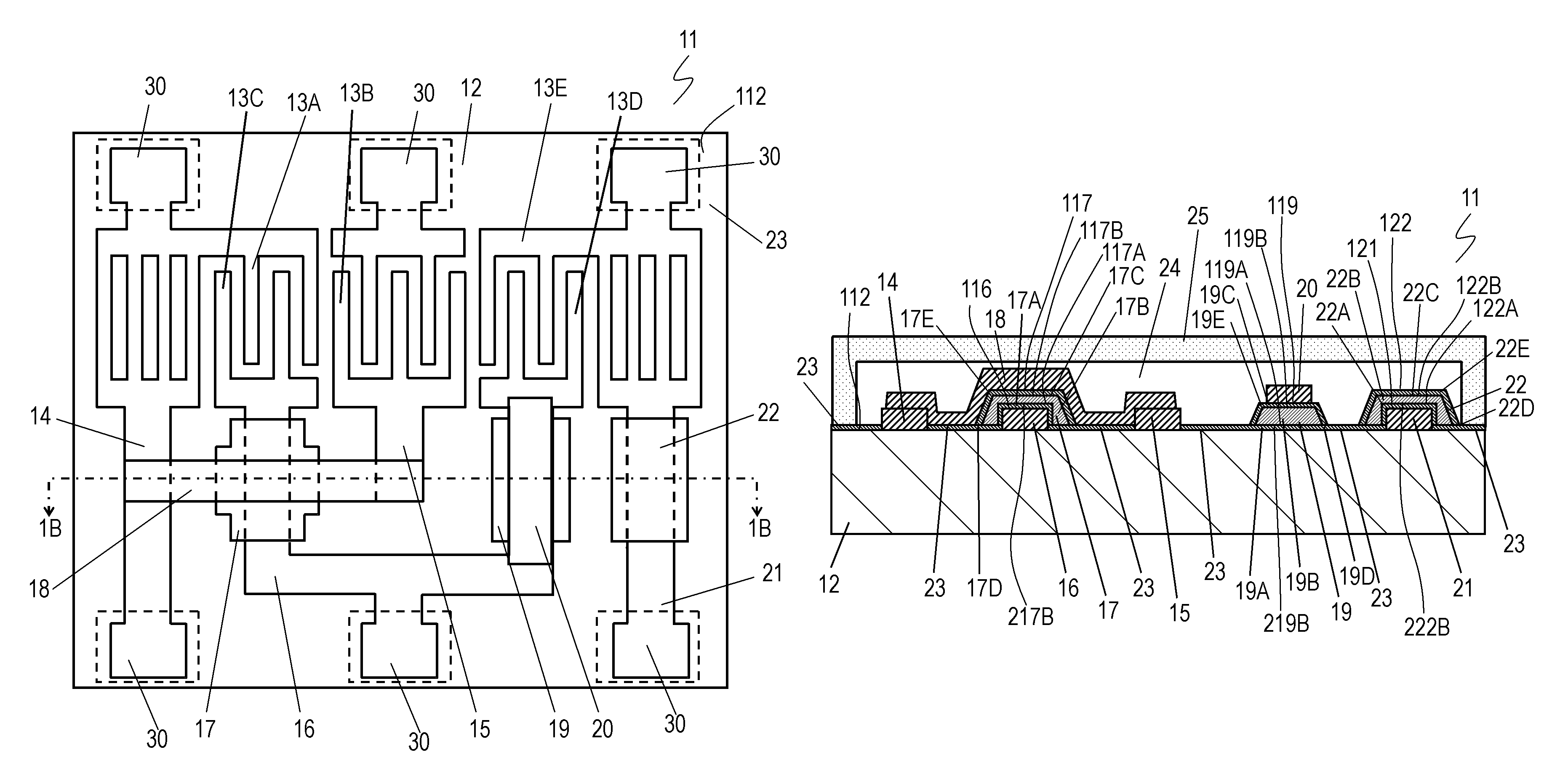
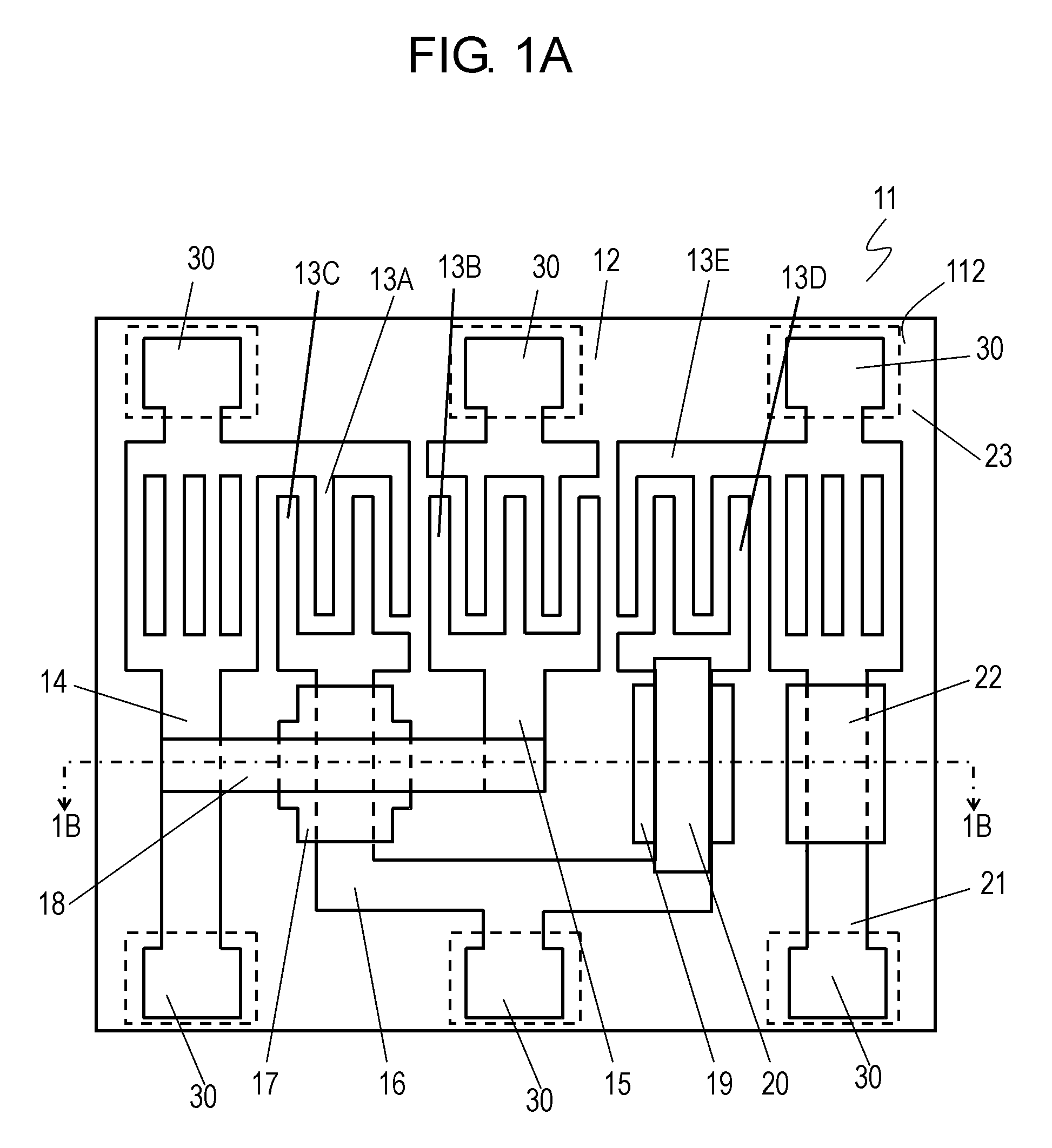
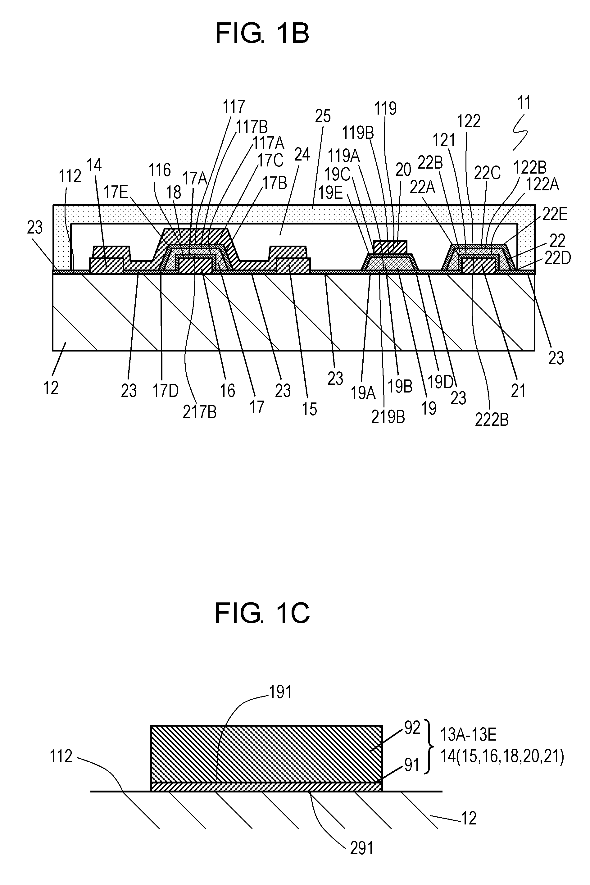
[0022]FIG. 1A is a top view of a piezoelectric substrate 12 of an acoustic wave device 11 according to Exemplary Embodiment 1 of the present invention. FIG. 1B is a cross sectional view of the acoustic wave device 11 along line 1B-1B shown in FIG. 1A.

[0023]The acoustic wave device 11 includes the piezoelectric substrate 12 and comb-shaped electrodes 13A to 13E disposed on an upper surface 112 of the piezoelectric substrate 12. The piezoelectric substrate 12 is made of a single crystal piezoelectric substance, such as lithium tantalate or lithium niobate. The comb-shaped electrodes 13A to 13E are arranged to excite an acoustic wave on the piezoelectric substrate 12 to allow the acoustic wave device 11 to constitute a filter circuit. The acoustic wave device 11 further includes wirings 14, 15, 16, 20, and 21 which are connected to the comb-shaped electrodes 13A, 13B, 13C, 13D, and 13E, respectively. The wirings 14, 15, 16, and 21 are disposed on the upper surface 112 of the piezoelect...

exemplary embodiment 2

[0046]FIG. 2A is an upper view of the piezoelectric substrate 12 of an acoustic wave device 61 according to Exemplary Embodiment 2 of the present invention. FIG. 2B is a cross sectional view of the acoustic wave device 61 along lines 2B-2B shown in FIG. 2A. FIG. 2C is a cross sectional view of the acoustic wave device 61 along line 2C-2C shown in FIG. 2A. In FIGS. 2A to 2C, components identical to those of the acoustic wave device 11 according to Embodiment 1 shown in FIGS. 1A to 1D are denoted by the same reference numerals.

[0047]The acoustic wave device 61 according to Embodiment 2 is different from the acoustic wave device 11 according to Embodiment 1 in that a wiring and an organic insulator are covered with a single inorganic insulator and face an oscillation space 24 across the inorganic insulator.

[0048]In the acoustic wave device 61, wirings 16 and 18 on the upper surface 112 of the piezoelectric substrate 12 cross one over the other across an organic insulator 26 between wir...


PUM


Abstract

An acoustic wave device includes a piezoelectric substrate, a first wiring disposed on an upper surface of the piezoelectric substrate, an organic insulator covering at least a portion of the first wiring, a second wiring disposed on a first portion of the upper surface of the organic insulator, and an inorganic insulator covering at least a second portion of an upper surface of the organic insulator. The second portion of the upper surface of the organic insulator faces an oscillation space across the inorganic insulator. The acoustic wave device has preferable high-frequency characteristics and high long-term reliability.

Description

[0001]THIS APPLICATION IS A U.S. NATIONAL STAGE APPLICATION OF THE PCT INTERNATIONAL APPLICATION NO. PCT / JP2011 / 000279.TECHNICAL FIELD[0002]The present invention relates to an acoustic wave device for use as a high-frequency filter in, for example, mobile communications devices.BACKGROUND ART[0003]In small communications apparatuses, such as mobile telephones, acoustic wave devices are commonly used as high-frequency filters having passing frequency range from tens of megahertz to several gigahertz.[0004]FIG. 3A is a top view of a piezoelectric substrate 2 of a conventional acoustic wave device 1. FIG. 3B is a cross sectional view of the acoustic wave device 1 along line 3B-3B shown in FIG. 3A. The acoustic wave device 1 includes the piezoelectric substrate 2 made of a single crystal piezoelectric substance, such as lithium tantalate or lithium niobate, and comb-shaped electrodes 3 disposed on a surface of the piezoelectric substrate 2. The acoustic wave device 1 forms a filter circ...

Claims


Application Information

Patent Timeline
Patent Type & Authority Patents(United States)
IPC IPC(8): H03H9/145H03H9/02H03H9/64
CPCH03H9/02992H03H9/02937
Inventor FURUKAWA, MITSUHIROKORECHIKA, TETSUHIROHARADA, SHINJI
Owner SKYWORKS PANASONIC FILTER SOLUTIONS JAPAN
Learn More