
Integrative atrial fibrillation ablation

a technology of atrial fibrillation and ablation, which is applied in the direction of catheters, surgical instruments for heating, sensors, etc., can solve the problems of asynchronous rhythm, difficult and time-consuming procedures, and disruption of the normal cardiac cycl

Active Publication Date: 2015-08-11
BIOSENSE WEBSTER (ISRAEL) LTD
View PDF29 Cites 57 Cited by
  • Summary
  • Abstract
  • Description
  • Claims
  • Application Information

AI Technical Summary

Benefits of technology

This approach enhances the accuracy and efficiency of ablation site selection, allowing for safer and more effective treatment of atrial fibrillation by reducing procedure time and enabling less experienced operators to perform the procedure with improved precision.

Problems solved by technology

Cardiac arrhythmias, such as atrial fibrillation, occur when regions of cardiac tissue abnormally conduct electric signals to adjacent tissue, thereby disrupting the normal cardiac cycle and causing asynchronous rhythm.
The procedure is challenging and time consuming.

Method used


Image

  • Integrative atrial fibrillation ablation
  • Integrative atrial fibrillation ablation
  • Integrative atrial fibrillation ablation

Examples


embodiment 1

Alternate Embodiment 1

[0071]With continued reference to FIG. 3, in this variant, the mapping process described in the third phase 87 is augmented by including a map of the contact force between the catheter and the endocardium during the electroanatomic mapping process (step 89). The cardiac catheter incorporates a pressure detector for sensing a mechanical force against the distal tip when engaging an ablation site. A contact for catheter of the sorted described in commonly assigned U.S. Pat. No. 8,926,604, which is herein incorporated by reference, may be used for this purpose. A suitable contact force catheter is available from Biosense-Webster as the THERMOCOOL® SMARTTOUCH™ Contract Force Sensing Catheter. Regions having points in which the contact force exceeds a threshold value are defined (CF regions). In these regions only local effects contribute are perceived in the sensor; far field effects are filtered out. A contact force of at least 7 g is suggested.

[0072]Reference is ...

embodiment 2

Alternate Embodiment 2

[0074]Reference is now made to FIG. 6, which is a portion of the flow chart shown in FIG. 3, and which has been modified in accordance with an alternate embodiment of the invention. In this embodiment, detection of ganglionated plexi is enhanced during the mapping of CFAE and dominant frequency sites as performed in step 93 (FIG. 3) by high frequency stimulation at step 117. Stimulation at 20 Hz, 12 Volts, with a pulse width of 10 ms is suitable. Typically, the use of high frequency stimulation is focused on areas in which ganglionated plexi are anticipated, based on registration of images acquired by the above-describe imaging techniques.

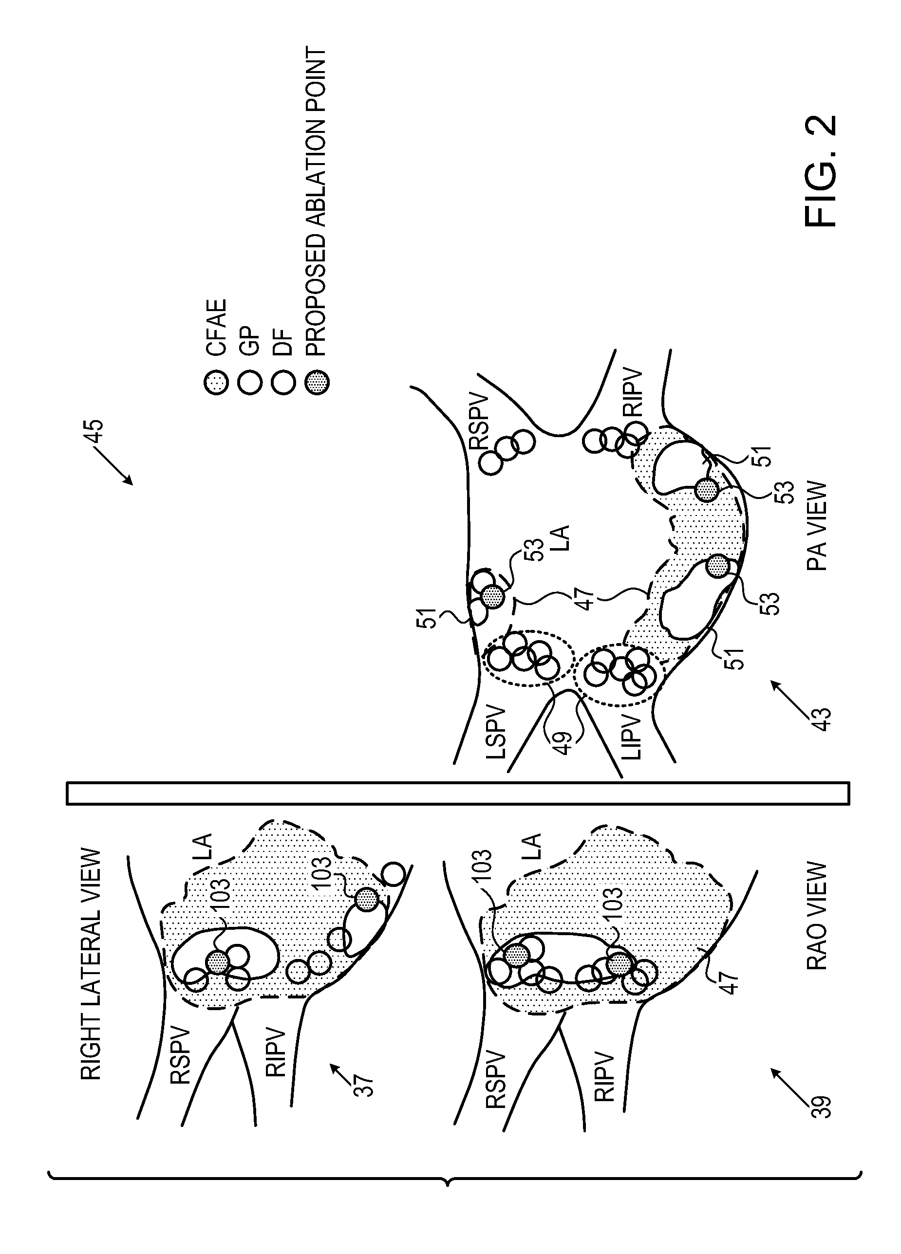
[0075]Step 117 defines first regions containing ganglionated plexi by the use of high frequency stimulation, second regions containing CFAE and dominant frequency sites as described above with reference to step 93 (FIG. 3).

[0076]Step 93 is performed to define first intersections of second regions (CFAE) with third regions (DF)...


PUM


Abstract

Cardiac tissue ablation is carried out by defining first regions containing first locations including ganglionated plexi in a heart of a living subject, and inserting a probe into the heart. The method is further carried out by detecting electrical activity in the heart via electrodes on the distal portion of the probe, defining second regions having second locations, wherein the electrical activity exhibits a dominant frequency that is higher than a predefined threshold, defining third regions having third locations, wherein the electrical activity exhibits complex fractionated atrial electrograms, constructing an electroanatomical map of the heart that defines intersections of the first regions and at least one of the second regions and the third regions, selecting ablation sites within the intersections, and ablating cardiac tissue at the ablation sites.

Description

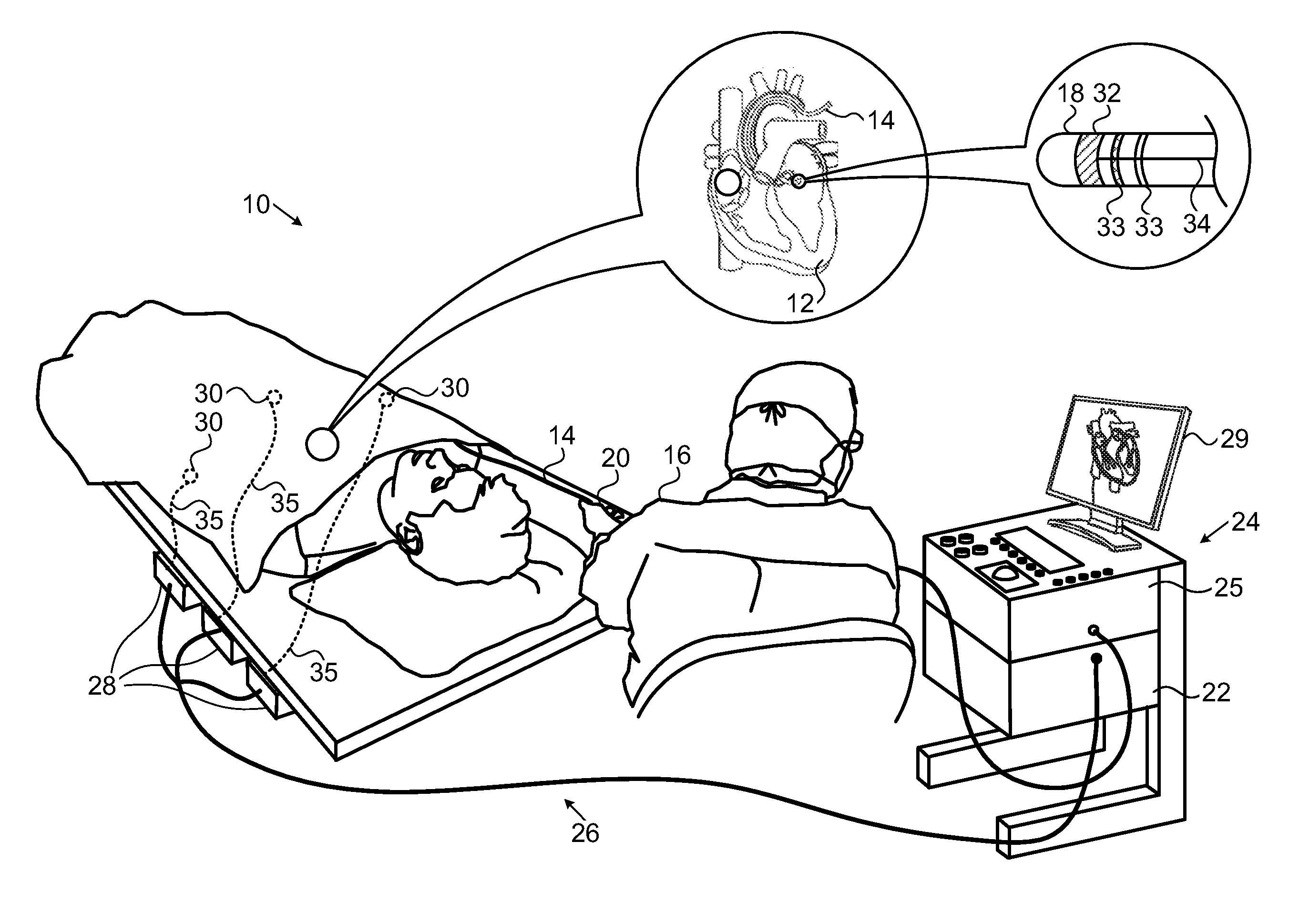
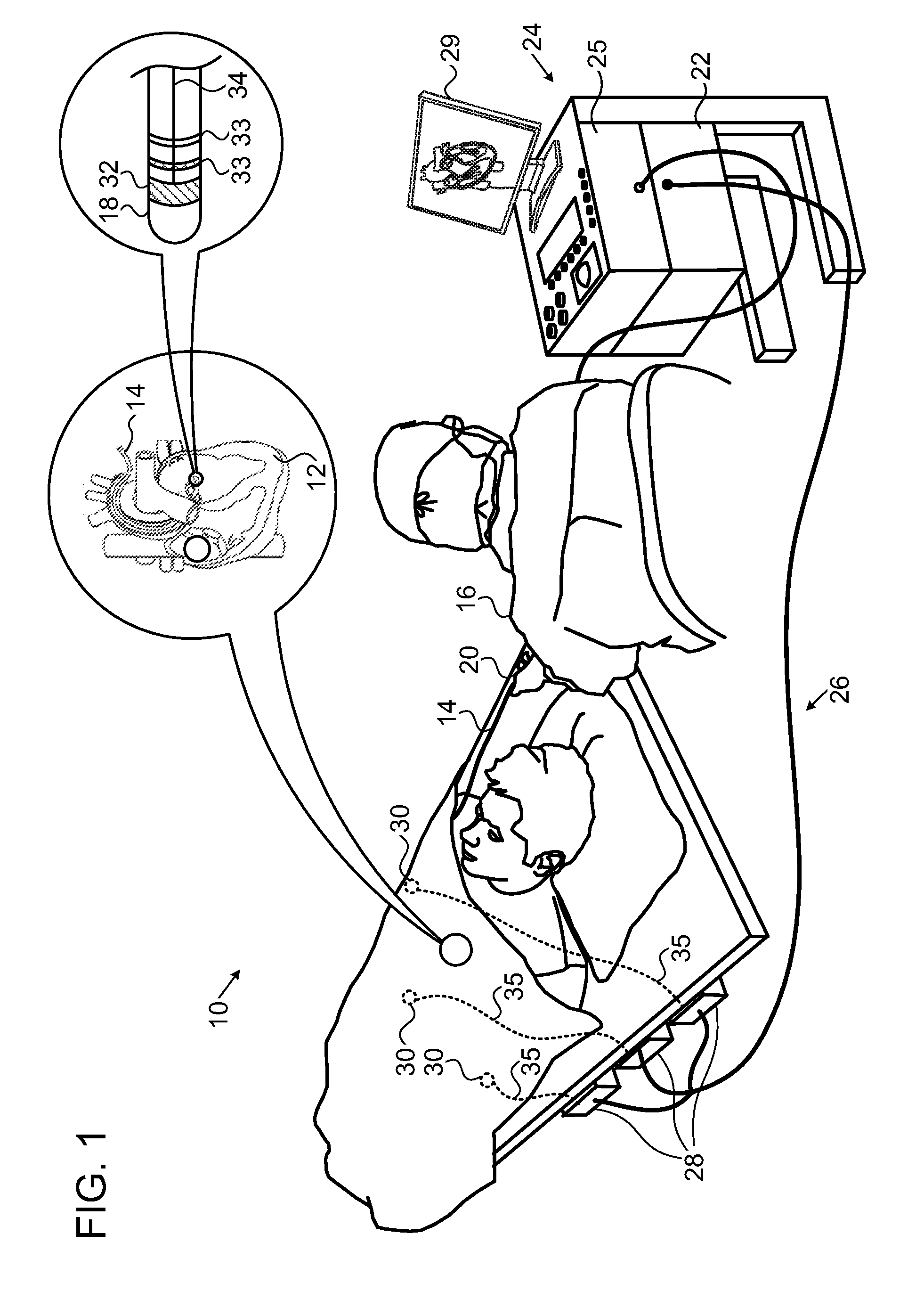
BACKGROUND OF THE INVENTION[0001]1. Field of the Invention[0002]This invention relates to relates generally to minimally invasive treatment of organs inside the body. More particularly, this invention relates to determination of ablation sites for ablation treatments applied to cardiac tissue.[0003]2. Description of the Related Art[0004]The meanings of certain acronyms and abbreviations used herein are given in Table 1.[0005]TABLE 1Acronyms and AbbreviationsAFAtrial FibrillationCFAEComplex Fractionated Atrial ElectrogramDFDominant FrequencyGPGanglionated PlexiLALeft AtriumMIBG123I-metaiodobenzylguanidineMRIMagnetic Resonance ImagingSPECTSingle Photon Emission Computed Tomography[0006]Cardiac arrhythmias, such as atrial fibrillation, occur when regions of cardiac tissue abnormally conduct electric signals to adjacent tissue, thereby disrupting the normal cardiac cycle and causing asynchronous rhythm.[0007]Procedures for treating arrhythmia include surgically disrupting the origin of ...

Claims


Application Information

Patent Timeline
Patent Type & Authority Patents(United States)
IPC IPC(8): A61B18/00A61B5/00A61B18/14A61B18/24A61B19/00A61B5/0452A61N7/02A61B5/296
CPCA61B5/7285A61N7/022A61B18/1492A61B18/24A61B19/5244A61B19/56A61B2018/00357A61B2018/00577A61B2019/465A61B2019/5289A61B2019/562A61B5/0452A61B34/20A61B34/25A61B2090/364A61B2090/065A61B2034/252A61B5/349A61B5/361
Inventor SCHWARTZ, YITZHACK
Owner BIOSENSE WEBSTER (ISRAEL) LTD
Learn More