Distance measuring device

a technology of distance measurement and measuring device, which is applied in the direction of distance measurement, instruments, surveying and navigation, etc., can solve the problems of increasing or worsening the noise term or snr, reducing the maximum possible measurement distance, and poorer snr, so as to improve the noise term or worsening of snr, increase the measurement accuracy, and the effect of high bandwidth

Active Publication Date: 2015-08-11
VECTRONIX AG
View PDF19 Cites 86 Cited by
  • Summary
  • Abstract
  • Description
  • Claims
  • Application Information

AI Technical Summary

Benefits of technology

[0037]In summary, the invention allows temporally short pulses to be used to attain greater measurement accuracy, these shorter pulses also requiring a correspondingly high bandwidth in the receiver. However, the high bandwidth also prompts an increase in the noise term or worsening of the SNR. This poorer SNR reduces the maximum possible measurement distance, since the received signal strength decreases as the target distance increases. Therefore, the invention uses temporally long pulses to increase the maximum possible measurement distance, specifically because they can be evaluated with a lower bandwidth and hence a reduced noise term or improved SNR.

Problems solved by technology

However, the high bandwidth also prompts an increase in the noise term or worsening of the SNR.
This poorer SNR reduces the maximum possible measurement distance, since the received signal strength decreases as the target distance increases.

Method used


Image

  • Distance measuring device
  • Distance measuring device
  • Distance measuring device

Examples


Embodiment Construction

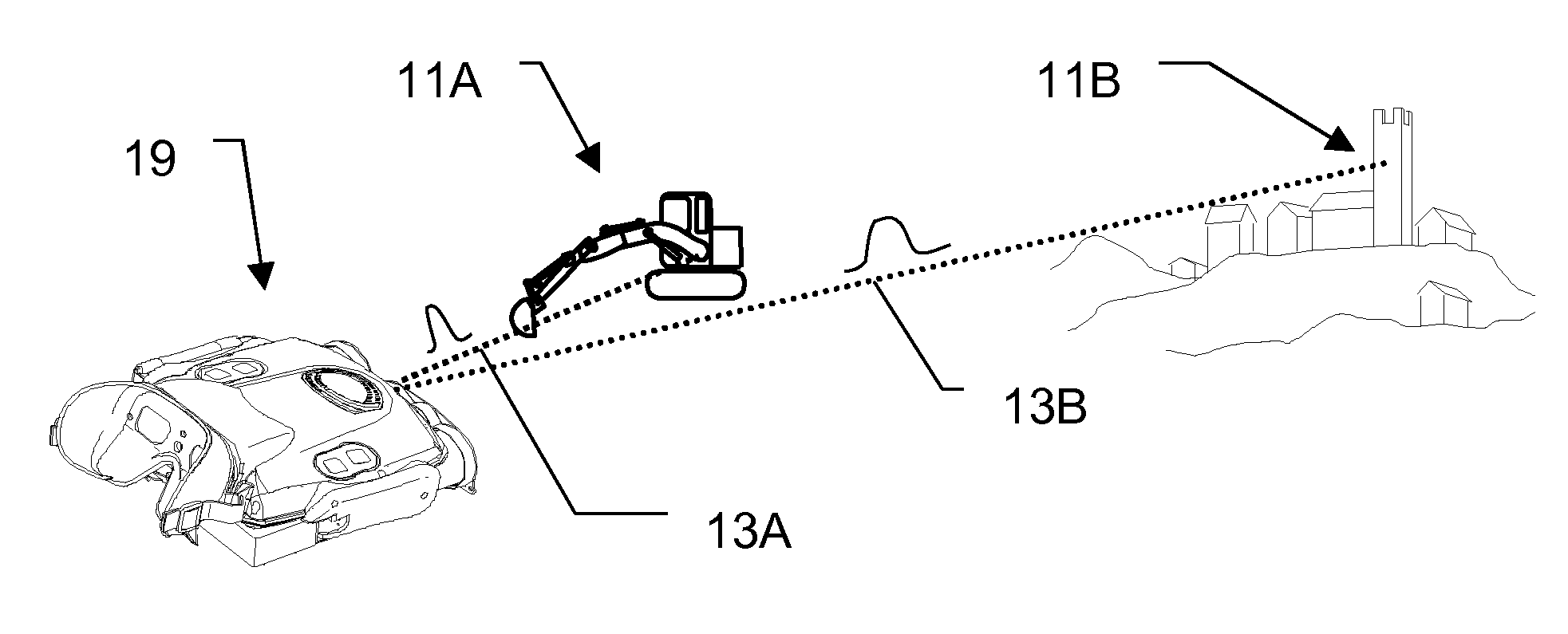
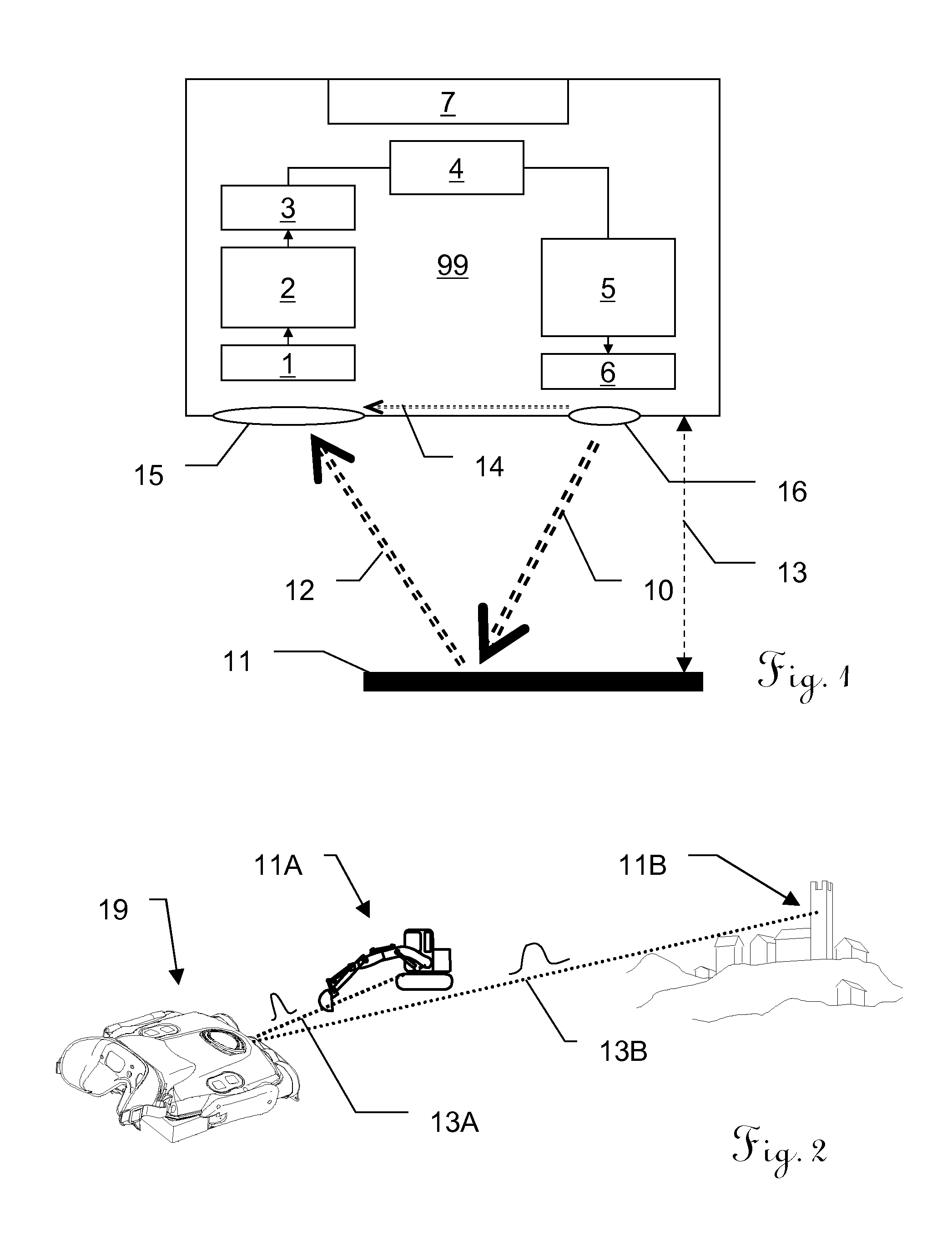
[0085]FIG. 1 shows an embodiment of an inventive optoelectronic distance measuring device 99 in the form of a block diagram. By way of example, this may be a battery operated distance measuring device which is fitted in an observation apparatus and which can be used for sighting and determining target coordinates for a target object 11. Alternatively, the principle according to the invention can be applied to other distance measuring devices, for example in surveying apparatuses.

[0086]The right-hand half of the distance measuring device block 99 shows the transmitting unit and the left-hand half shows the receiving unit. The separation between the two units which is described here can be seen primarily on a functional basis in this case and may (but does not have to) be designed in the form of two physically separate units. It is possible to produce embodiments in which both units are accommodated on a shared printed circuit board, and also embodiments in which the components of the...


PUM


Abstract

An optoelectronic distance measuring device is disclosed. The device has a transmitting unit with a driver stage for emitting optical pulses, a receiving unit for receiving a portion of the optical pulses, said portion being reflected from a target object, and converting it into an electrical reception signal, via a photosensitive electrical component. It also has an analog-digital converter for digitizing the reception signal, and an electronic evaluation unit to ascertain a distance from the target object on the basis of a signal propagation time using the digitized reception signal. The driver stage can be designed so that at least two pulse durations of different length for the optical pulses can be set.

Description

[0001]This application claims priority to European Patent Application No. 12158382.7, which was filed in Europe on Mar. 7, 2012, and which is herein incorporated by reference in its entirety.BACKGROUND OF THE INVENTION[0002]1. Field of the Invention[0003]The invention relates to a distance measuring device according to the preamble of Claim 1 and to a distance measuring method according to the preamble of Claim 9.[0004]2. Description of the Background Art[0005]In electro-optical distance measuring devices (EDM), an optical signal is emitted from the apparatus in the direction of the target object whose distance it is necessary to determine, for example as optical radiation in the form of laser light. If visible light is used in this case, then the point aimed at for measurement on the target object can be visually discerned. By contrast, if non-visible wavelengths, e.g. in the infrared range, are used or if the target object is further away, then aiming at the point to be measured c...

Claims


Application Information

Patent Timeline
Patent Type & Authority Patents(United States)
IPC IPC(8): G01C3/08G01S17/10G01S7/484G01S7/486G01S7/4865
CPCG01C3/08G01S17/10G01S7/484G01S7/4865
Inventor GIACOTTO, LUCATINIVELLA, RICCARDO
Owner VECTRONIX AG
Why Eureka
Try Eureka