Optical transmission and receiving device for implementing passive alignment of components and method for passively aligning components

a technology of optical transmission and receiving device and passive alignment, which is applied in the direction of optical elements, instruments, manufacturing tools, etc., can solve the problems of time-consuming manufacturing process, difficult use of optical alignment device, and inability to achieve passive alignment, so as to reduce the structure of optical modules, simplify passive optical alignment, and minimize alignment errors

Active Publication Date: 2015-08-11
CELLCUBES CO LTD
View PDF34 Cites 4 Cited by
  • Summary
  • Abstract
  • Description
  • Claims
  • Application Information

AI Technical Summary

Benefits of technology

[0014]According to the present invention, the optical fiber 133a is aligned in close contact with a surface 122b of the prism 122, so that there is no additional structure required for aligning the optical fiber 133a, and the amount of reflection loss can be reduced at the reflective surface 122b by index matching epoxy.
[0015]Also, the lens-optical fiber connection part 120 includes a focusing lens 123 for collecting and guiding the light, a prism 122 which alters the traveling direction of the light, and an optical fiber connector 121 which secures and aligns the optical fiber 133, formed in a single structure, so that the number of parts may be reduced.
[0016]Thus, the present invention provides the advantages of simplifying passive optical alignment for multiple channels, so as to minimize alignment error, and of reducing and simplifying the structure of the optical modules and minimizing the number of parts used, so as to lower the costs of the optical modules.
[0017]Since it is not necessary to apply large, complicated precision equipment for the optical alignment, the time required for the optical alignment can be reduced, and accurate alignment is guaranteed every time, providing benefits in terms of efficiency and convenience.
[0018]In addition, the present invention makes it possible to mass produce bi-directional optical devices that are simple both in structure and assembly method, so that data communication speeds at home or at the office can be improved with low costs, laying the foundations for greater advances in the Internet.

Problems solved by technology

In conventional methods of signal transmission based on fiber optics, however, the optical device for coupling the light-emitting elements with the optical fiber or for coupling the light emitted from the optical fiber with the light-receiving elements is not only very expensive but also quite difficult to use in performing optical alignment.
This method of active optical alignment, in which the light-emitting element or light-receiving element is driven directly and the degree of alignment with the optical fiber is sensed in real time to yield the optimum degree of alignment, requires a time-consuming manufacture process and expensive assembly apparatus.

Method used


Image

  • Optical transmission and receiving device for implementing passive alignment of components and method for passively aligning components
  • Optical transmission and receiving device for implementing passive alignment of components and method for passively aligning components
  • Optical transmission and receiving device for implementing passive alignment of components and method for passively aligning components

Examples


Embodiment Construction

[0051]Specific embodiments of the present invention are described below with reference to the accompanying drawings.

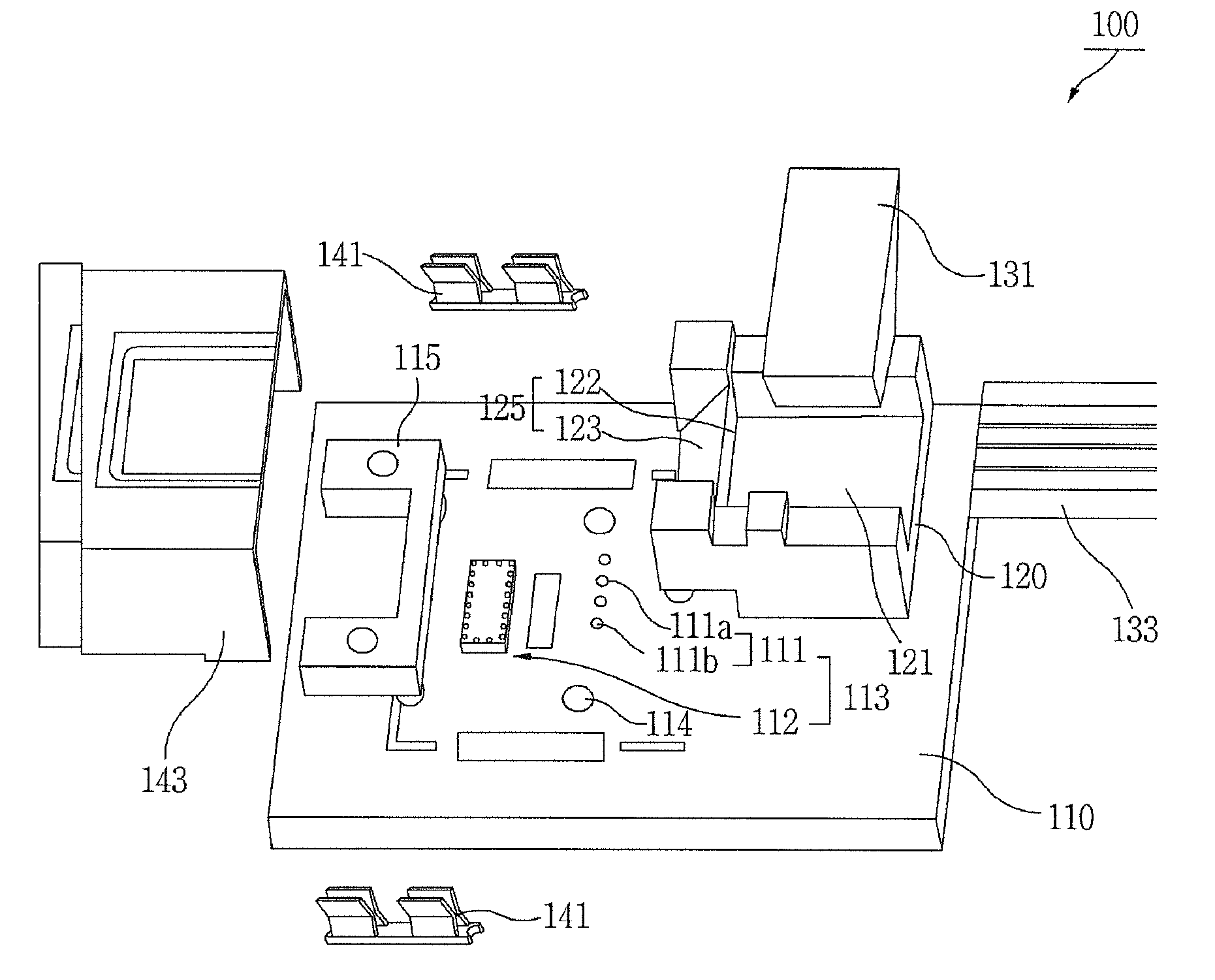
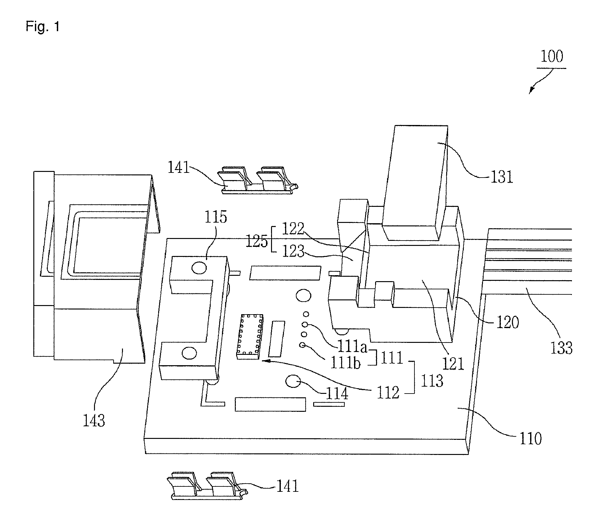
[0052]FIG. 1 illustrates the constitution of an optical device according to the present invention.

[0053]Referring to FIG. 1, an optical device 100 of the present invention includes a substrate 110, an optical element part 111 that includes light-emitting elements 111a and light-receiving elements 111b, a driver circuit 112, a photoelectric converter part 113 that includes the optical element part and the driver circuit 112, substrate holes 114, an alignment reference part 115 arranged on the substrate 110 for passively aligning the optical element part 111 and the lens-optical fiber connection part 120, a lens-optical fiber connection part 120 for collecting light, altering the optical path, and securing and aligning the optical fiber 133, an optical fiber pin 131 connected to one end of the lens-optical fiber connection part 120, an optical fiber 133 for implementing ...


PUM

PropertyMeasurementUnit
transparentaaaaaaaaaa
refractive indexaaaaaaaaaa
densityaaaaaaaaaa

Abstract

An optical device for implementing passive alignment of parts and a method therefore, more particularly an optical device and a method therefore that utilize an alignment reference part 115 arranged on the substrate 110 to passively align an optical element part 111 with a lens-optical fiber connection part 120. For the passive alignment of parts, connection pillars 115b of an alignment reference part 115 are coupled to substrate holes 114, one or more light-emitting elements 111a and one or more light-receiving elements 111b are aligned in a row in a particular interval with respect to alignment holes 115a arranged opposite each other in the alignment reference part 115, a lens-optical fiber connection part 120 is aligned with respect to the alignment holes 115a, and an optical fiber 133 is aligned with the optical alignment point at a surface 122b of a prism forming a portion of the lens-optical fiber connection part 120. In addition, the optical fiber 133 is secured with an optical fiber pin 131, after which a metal case 143 is covered and coupled with a case securing pin 141. The optical device for implementing passive alignment of parts provides the advantages of simplifying the passive optical alignment for multiple channels, so as to minimize alignment error, and of reducing and simplifying the structure of the optical modules and minimizing the number of parts used, so as to lower the costs of the optical modules.

Description

CROSS-REFERENCE TO RELATED APPLICATIONS[0001]This application is a United States National Stage Application under 35 U.S.C. §371 of International Patent Application No. PCT / KR2011 / 006902, filed Sep. 19, 2011, which claims the benefit to Korean Patent Application No. 10-2010-0091614, filed Sep. 17, 2010, each of which is incorporated by reference into this application as if fully set forth herein.TECHNICAL FIELD[0002]The present invention relates to an optical device for implementing passive alignment of parts and a method therefore, more particularly to an optical device and a method therefore that utilize an alignment reference part arranged on the substrate to passively align an optical element part with a lens-optical fiber connection part.BACKGROUND ART[0003]Methods of signal transmission based on fiber optics, which are already widely used in long-distance communication, provide the advantages of broad bands and immunity to electromagnetic interference (EMI), and are thus being...

Claims


Application Information

Patent Timeline
Patent Type & Authority Patents(United States)
IPC IPC(8): G02B6/12G02B6/34G02B6/26G02B6/42G02B6/32
CPCG02B6/4214G02B6/423G02B6/4244G02B6/26G02B6/32G02B6/34G02B6/4243G02B6/4245G02B6/4249G02B6/4277Y10T29/49895G02B6/4206G02B6/4231G02B6/4239G02B6/424G02B6/425G02B6/4257
Inventor SON, YUNG SUNGLEE, SANG-SHINLEE, HAK-SOONPARK, JUN-YOUNG
Owner CELLCUBES CO LTD
Why Eureka
Try Eureka