
System for achieving selectable fixation in an orthopedic plate

a technology of selectable fixation and orthopedic plates, which is applied in the field of orthopaedic plates and fastener systems, can solve the problems of overly rigid locking structures, complex interactions between the fasteners, typically screws or pegs, and the plate, and achieve the effect of improving the strength of fixation and improving the locking

Active Publication Date: 2015-08-25
ORTHOHELIX SURGICAL DESIGNS
View PDF66 Cites 46 Cited by
  • Summary
  • Abstract
  • Description
  • Claims
  • Application Information

AI Technical Summary

Benefits of technology

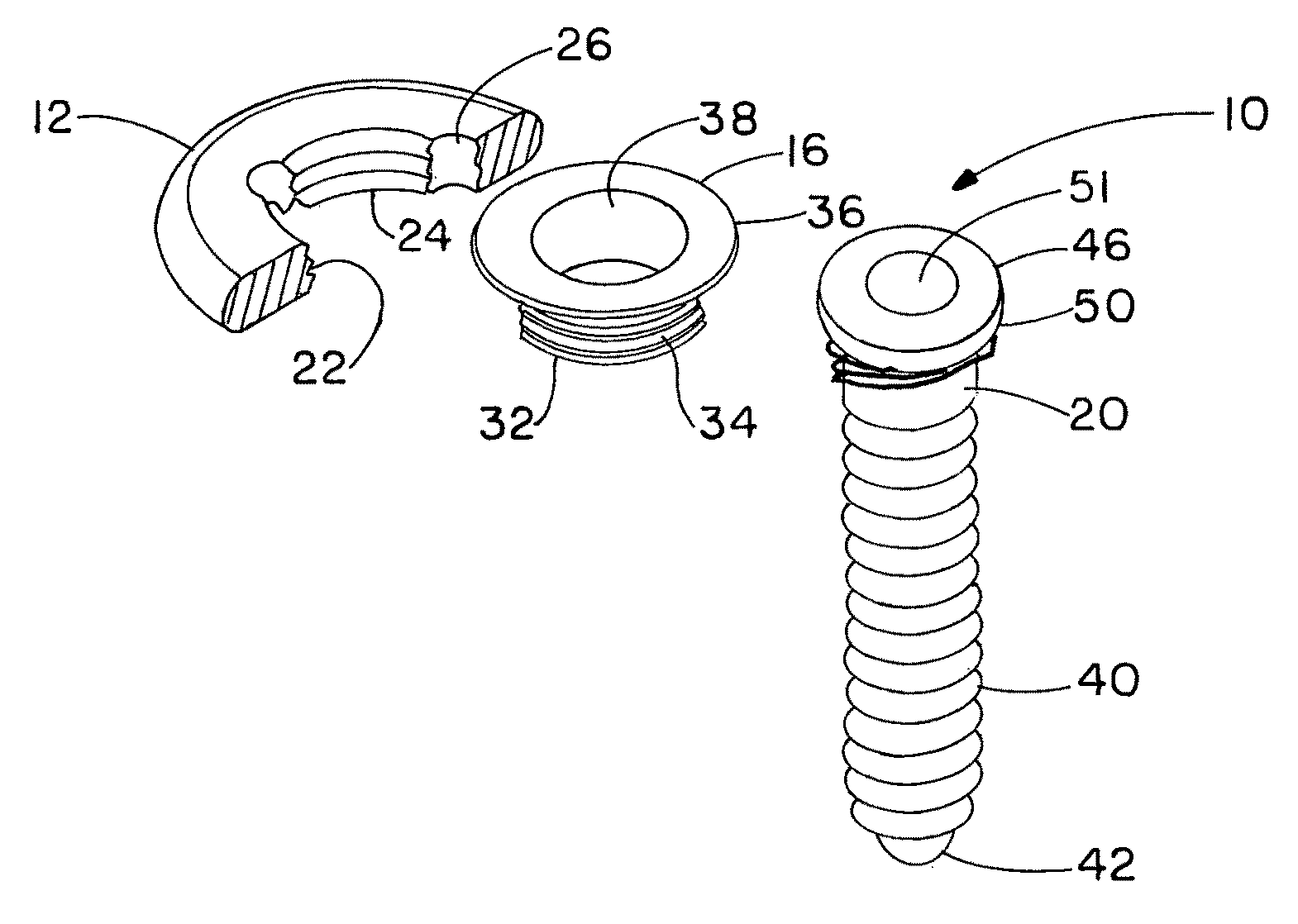
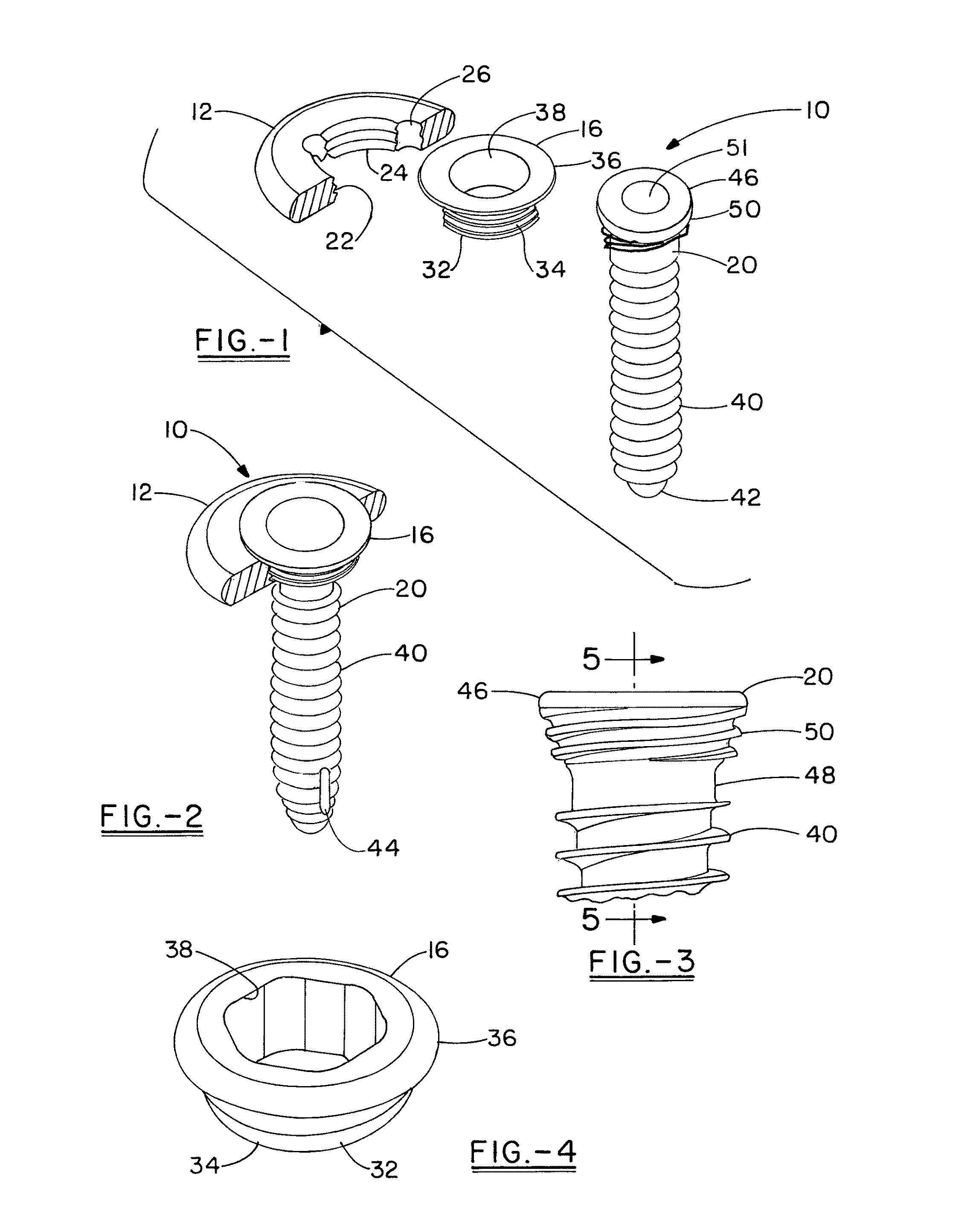
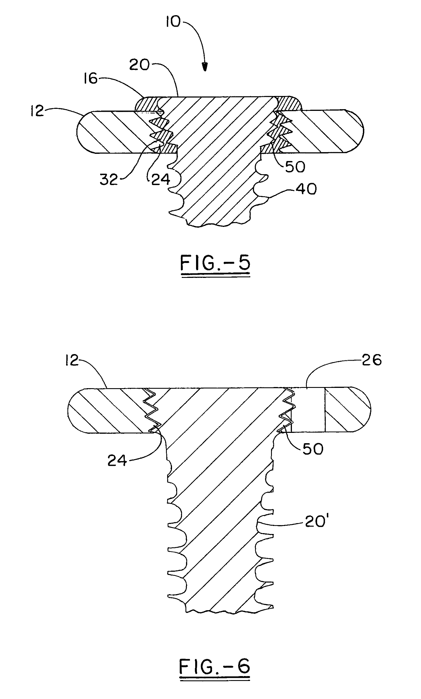
[0013]The present invention provides a system of orthopedic plates and fasteners which provides for selectable fixation between three modes of fixation, i.e. fixed angle locking fixation, variable angle locking fixation, and non-locking fixation all within a single fastener opening. One aspect of the present invention includes a variable locking assembly that has a locking insert that is threaded into, and thus mechanically seated in, the internally threaded opening in an implant. The locking insert has an annular flange or shoulder that surrounds the opening in the implant on the superior surface, and also has a central through opening that is preferably smooth and hexagonal in cross section to allow the insert to be screwed into the plate opening. The locking insert is made from a biocompatible material that can be deformed by the threads of the fastener head, (i.e. a screw or peg,) so that the fixator is inserted through the locking insert and into the adjacent bone to the point where the proximal head threads interact with the internal opening of the locking insert to cause the material to flow and accept the head of the fastener at any angle (up to ˜20°) while maintaining a rigid construct. Both the minor diameter and the major diameter of the screw head include a taper to improve the locking within the locking insert. Preferably, the major diameter of the threads taper out at a larger angle than the minor diameter, i.e. by a difference of from about 2° to about 20°, preferably from about 5° to about 15°, and preferably about 8° to about 12° degrees of difference so that the threads widen at a greater rate than the head does to improve the strength of the fixation when the fastener is locked into the insert. The invention further includes a tool for insertion of the locking insert into the plate. The insert can be provided on the tool, which has a friction fit, such as a tapered head split that compresses to hold the insert and allow the insert to be threaded into the screw hole of the plate. The tool is advantageously made of plastic, and is a single use device.

Problems solved by technology

The interaction of the fasteners, which are typically screws or pegs, with the bone, and with the plate is a complex matter.
While these types of plates, known as “locking plates”, have become the standard of care in both reconstructive and trauma plating, there is evidence within the medical community, that there are some potential problems with overly stiff locking constructs.
There is growing evidence that some locking constructs have become too stiff to allow for proper bone healing.
Current solutions on the market do provide the ability to vary the angle of the locking screws, but they do so by significantly compromising the strength of the interaction between the plate and the screw.
This creates a greatly weakened overall construct when compared to a traditional fixed angle locking construct.
This leaves all of the plate holes compromised even if the nominal angle of the screw hole would have been appropriate.
Further, increasing the strength reduces the chance of construct failure and resultant non-union of the fixed bones.
This has serious consequences for both the surgeon and the patient being treated.

Method used


Image

  • System for achieving selectable fixation in an orthopedic plate
  • System for achieving selectable fixation in an orthopedic plate
  • System for achieving selectable fixation in an orthopedic plate

Examples


Embodiment Construction

[0036]FIG. 1 shows an exploded view of a variable axis locking mechanism assembly in accordance with the present invention that is further illustrated in FIGS. 2 through 5. FIG. 5 shows a cross section of the assembly of FIG. 1. The assembly 10 includes an implant member that is shown as a plate 12, a locking insert 16 and a variable locking fastener, which is shown as a screw 20. For the purpose of this description, the plate is shown in FIGS. 1, 2, 5, and 6 as part of an annular portion of a plate including a through hole 22 with internal threads 24, and optionally grooves 26 that act as seats for a drill guide. The plate could have any appropriate shape according to the application with which it is used, distal radius plates, calcaneal plates, long bone plates, plates for the clavicles, spinal plates, plates for use in the hand and foot, or any other surgical implant and accordingly is illustrated in FIGS. 7-9 as having a modified X-shape where the plate has diagonally opposed pa...


PUM


Abstract

An orthopedic plate and fastener system is provided for fixation of bones which has an implant that can selectably be used to achieve fixed angle and variable locking of the fasteners, as well as non-locking of the fasteners. The system includes a variable locking assembly that includes a locking insert, having threads which mates with internal threads of a through opening in the implant. The system also provides for locking fixed angle fixation, and non-locking variable angle fixation, all of which can be used with the threaded holes of the plates. The locking insert is provided on a ring driver, which is similar to or acts as the drill guide used with the locking fasteners of the present. Thus, the invention also relates to a method of enabling surgery where the surgeon can select the mode of fixation of fasteners between variable axis locking, variable axis non-locking, and fixed angle locking fixation, all utilizing the same fastener opening within the implant.

Description

CROSS-REFERENCE[0001]This Application claims the benefit of priority under 35 U.S.C. §119 of U.S. Provisional Application Ser. No. 61 / 339,857, filed on Mar. 10, 2010, herein fully incorporated by reference.FIELD OF THE INVENTION[0002]The present invention relates to an orthopedic plate and fastener system for fixation of bone, and further in particular to an orthopedic plate and fastener system which can selectably be used without substantial modification to surgical procedure to achieve fixed angle and variable locking of the fasteners, as well as variable angle non-locking of the fasteners, all within the same fastener opening of the plate.BACKGROUND OF THE INVENTION[0003]The use of ORIF (Open Reduction, Internal Fixation) has become a mainstay in the treatment of a variety of medical conditions. The corresponding design of orthopedic implants used to achieve this fixation has progressed through the development of plates or other stabilization means, including for example rods and...

Claims


Application Information

Patent Timeline
Patent Type & Authority Patents(United States)
IPC IPC(8): A61B17/80A61B17/17A61B17/86A61B17/88
CPCA61B17/8047A61B17/1728A61B17/8057A61B17/8615A61B17/8888A61B17/861
Inventor LEWIS, DEREK S.LEITHER, ANDREW J.DILIBERTO, REBECCA F.
Owner ORTHOHELIX SURGICAL DESIGNS
Learn More