
Rotating platform for wheelchair bound people

a technology for turning tables and wheelchairs, which is applied in the direction of wheelchairs/patient conveyances, machine supports, furniture parts, etc., can solve the problems of insufficient safety considerations, difficult maneuverability in tight quarters, and insufficient attention to modern, motorized and therefore heavy wheelchair applications

Active Publication Date: 2015-08-25
CALLAHAN RONALD J
View PDF17 Cites 4 Cited by
  • Summary
  • Abstract
  • Description
  • Claims
  • Application Information

AI Technical Summary

Benefits of technology

Enables safe and convenient operation of wheelchairs in tight spaces and during vehicle motion, with automatic power and control transfer, ensuring the wheelchair-bound person has full control over the turntable's operation, enhancing safety and usability.

Problems solved by technology

Conventional wheelchairs or powerchairs, in particular rear wheel drive chairs, are not designed to rotate on a central axis and are difficult to maneuver in tight quarters and cannot rotate or turn on a short axis like modern mid wheel drive powerchairs which can rotate on a short axis.
However, the rear wheel drive powerchairs are far more suitable for travel over rough terrain such as in fields or in wooded areas.
However, safety concerns have not been sufficiently addressed.
Moreover, applications for modern, motororized and therefore heavy wheelchairs have also not been sufficiently addressed.
However, no provisions are made to secure the wheelchair itself, much less the occupant.
In operation, the shaft is fitted with a retaining washer which permits rotation but does not permit the shaft to be pulled out of the opening.
The wheelchair is rolled onto the platform but is in no way secured to the platform.
However, these stops, which are permanently fastened to the platform, make it difficult to subsequently move the wheelchair off the platform.

Method used


Image

  • Rotating platform for wheelchair bound people
  • Rotating platform for wheelchair bound people
  • Rotating platform for wheelchair bound people

Examples


Embodiment Construction

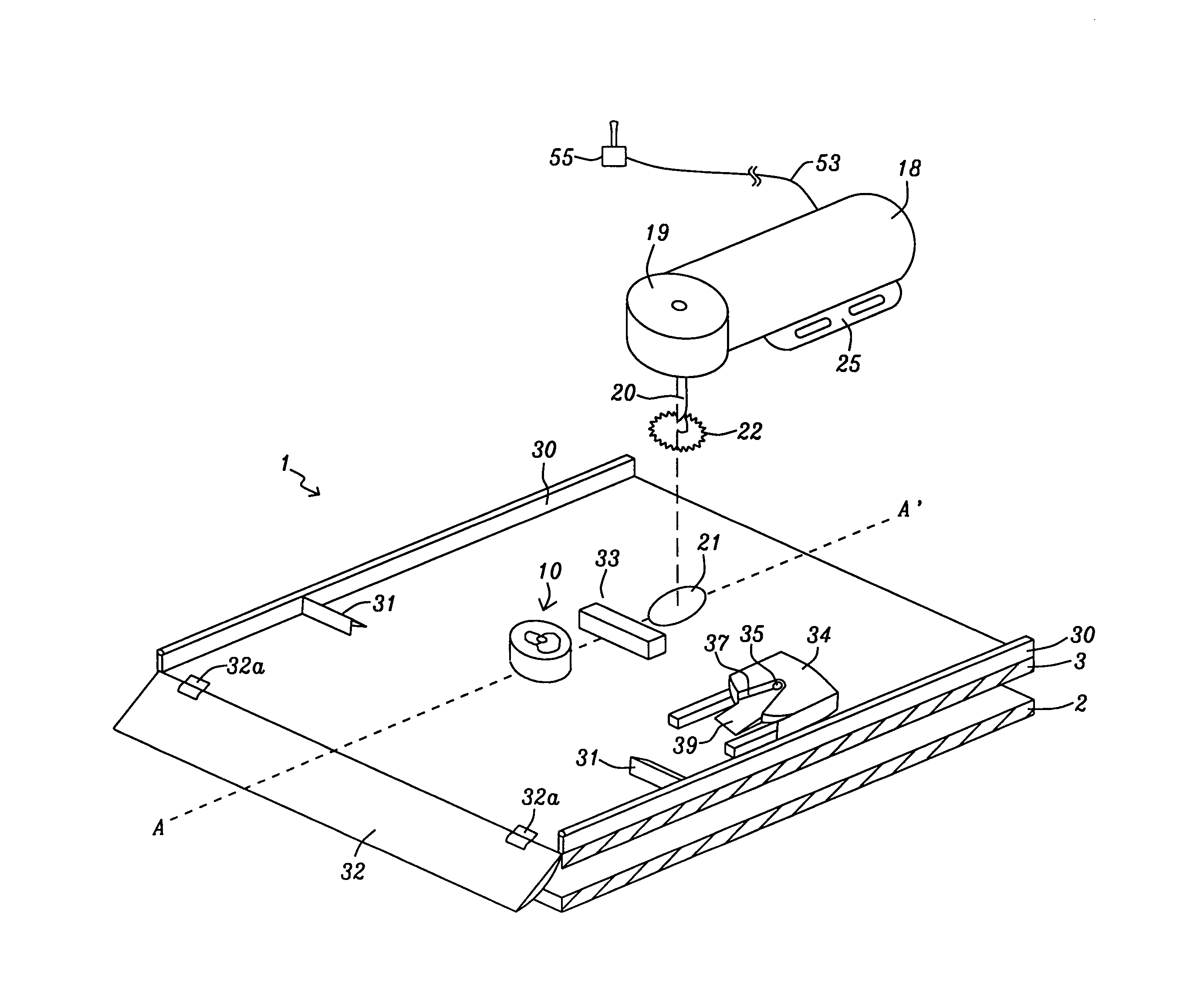
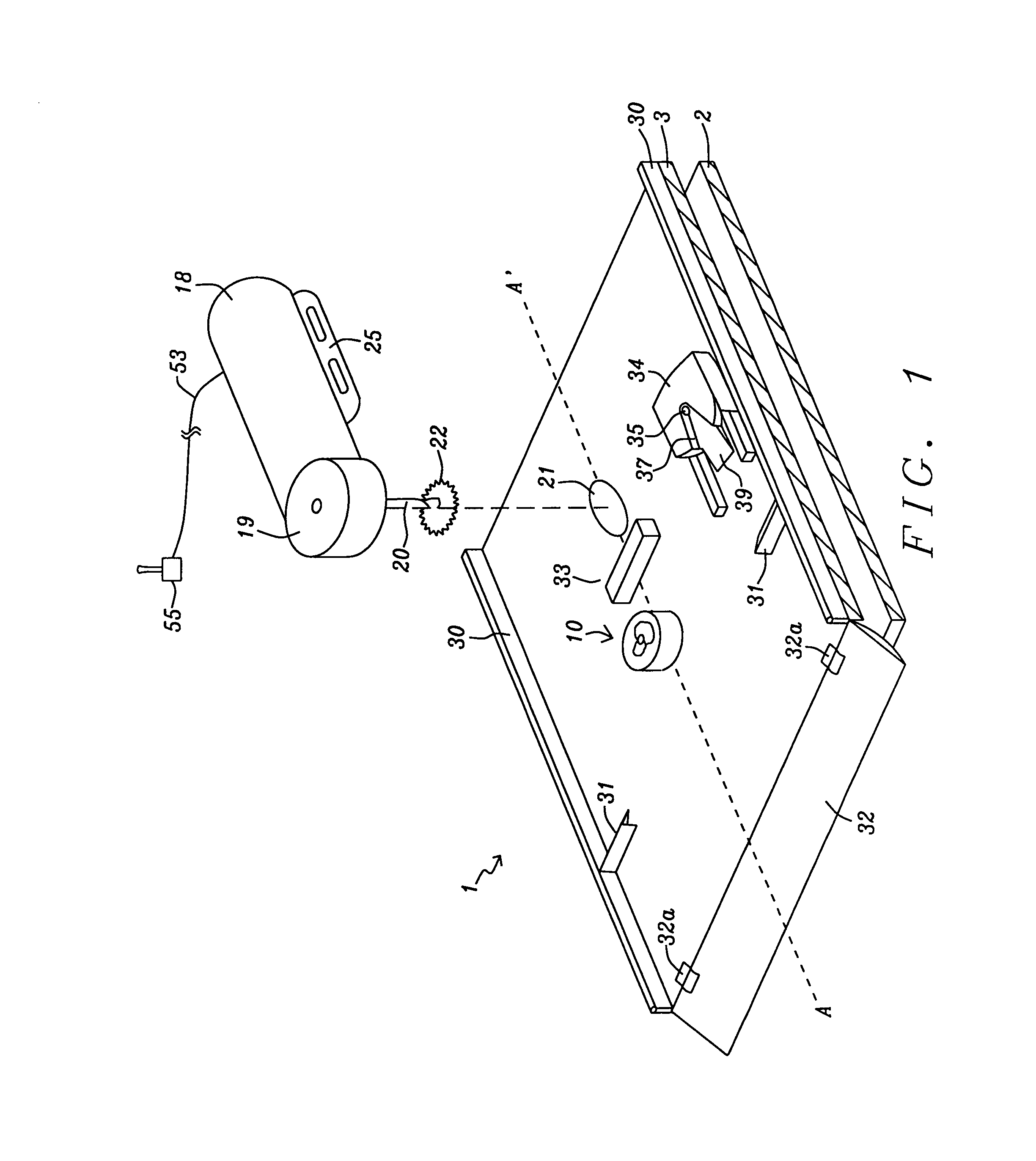
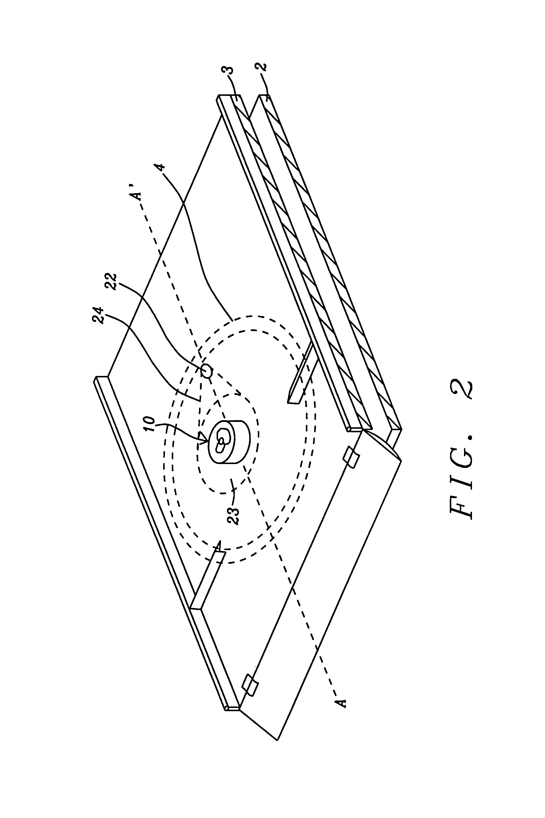
[0027]A preferred embodiment of this invention is illustrated in FIGS. 1-3. Referring first to FIG. 1, there is shown a platform 1 consisting of a stationary base plate 2 and a rotatable top plate 3. Plates 2 and 3 are preferably constructed of aluminum and have a thickness of ⅜ inch or thereabout and dimensions of about 2 feet in width and about 3 feet in length. These dimensions are determined by the size of the wheelchair to be accommodated. Alternatively, the plates 2 and 3 could be constructed of titanium or magnesium. The bottom (stationary) race 6 of a large circular ring thrust bearing 4, shown in phantom in FIG. 2 and in cross-section in FIG. 3, is secured to the bottom plate 2 by screws 6a. The upper plate 3 rests upon nylon, or alternately Teflon, pads 5 (shown in FIG. 3) which are fastened onto the top race 7 of the thrust bearing 4 with an adhesive.

[0028]The thrust bearing has a weight capacity of about 850-1000 pounds and is only about ¾ inches in height. The large bea...


PUM


Abstract

A method and apparatus for rotating a wheelchair on a motorized rotatable platform comprising providing a motorized rotatable platform comprising a stationary bottom plate and a rotatable top plate supported by a central conical bearing assembly and a circular ring thrust bearing, wherein rotation of the top plate is accomplished by an electric motor / gearbox assembly fastened onto the top plate, driving the wheelchair onto the motorized rotatable platform, anchoring the wheelchair to the top plate and switching electrical power from the wheelchair's electric motor to the electric motor / gearbox assembly, rotating the wheelchair to a desired position using the wheelchair's controls, and disengaging anchoring of the wheelchair and switching electrical power back to the wheelchair's electric motor, and driving the wheelchair off the platform.

Description

[0001]This application is a Continuation-in-Part application of U.S. Ser. No. 12 / 322,152, filed on Jan. 29, 2009 now abandoned, which is herein incorporated by reference in its entirety.BACKGROUND OF THE INVENTION[0002](1) Field of the Invention[0003]The invention relates to the design and operation of a lightweight portable turntable for rotating a wheelchair in tight quarters.[0004](2) Description of Related Art[0005]Conventional wheelchairs or powerchairs, in particular rear wheel drive chairs, are not designed to rotate on a central axis and are difficult to maneuver in tight quarters and cannot rotate or turn on a short axis like modern mid wheel drive powerchairs which can rotate on a short axis. However, the rear wheel drive powerchairs are far more suitable for travel over rough terrain such as in fields or in wooded areas. Situations are encountered wherein the ability to rotate a wheelchair in tight quarters is required in sporting events wherein travel over rough terrain ...

Claims


Application Information

Patent Timeline
Patent Type & Authority Patents(United States)
IPC IPC(8): A47B91/00A47B95/00A61G5/10A61G3/02
CPCA61G5/10A61G3/02A61G2005/1051A61G5/1051
Inventor CALLAHAN, RONALD J
Owner CALLAHAN RONALD J
Learn More