Externally-orientated internally-corrected perforating gun system and method

Active Publication Date: 2015-08-25
GEODYNAMICS +1
View PDF13 Cites 28 Cited by
  • Summary
  • Abstract
  • Description
  • Claims
  • Application Information

AI Technical Summary

Benefits of technology

[0035]Provide for a better than + / −15 degrees accuracy to reduce tortuosity and increase well performance.
[0036]Provide for preventing perforation in a random direction used in conventional bearings and roller mechanism.
[0037]Provide for maximizing charge size in order to achieve maximum perforation efficiency.
[0038]Provide for maximizing the number of charges by using the length of the perforating guns to maximize shot density.
[0040]Provide for a reliable and simple thorough wire to enable select fire systems with external or internal swiveling orienting guns
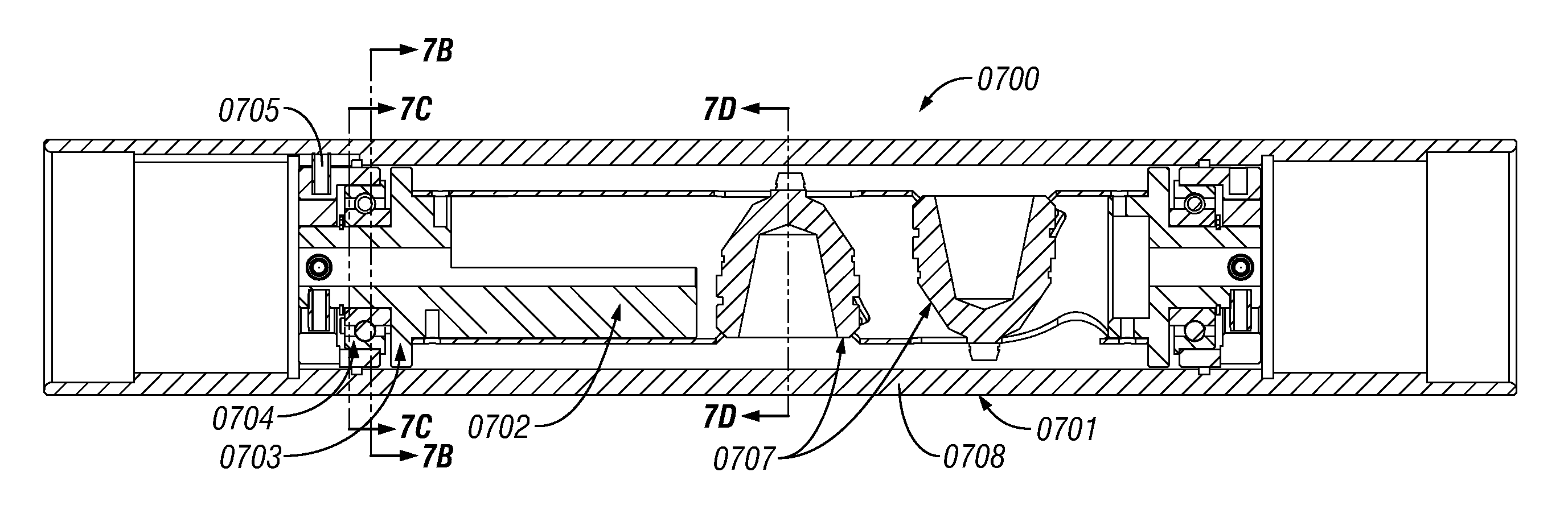
[0042]The present invention in various embodiments addresses one or more of the above objectives in the following manner. The present invention provides an externally-oriented internally-corrected system that includes a gun string assembly (GSA) deployed in a wellbore with an external protuberance member (EPM) and an internal pivot support (IPS). The EPM is oriented to the high side of the wellbore so that the center of mass of the GSA positions the GSA at the lower side of the wellbore surface. The internal components of the GSA swing / swivel from the IPS such that the charges are oriented towards a desired perforating orientation. The charges inside the GSA move with the gravitational vector and point more accurately in the desired direction for perforating. The external orientation of the EPM along with limited internal swing about the IPS provide for an accurate orientation of the charges for perforating through a hydrocarbon formation.Method Overview

Problems solved by technology

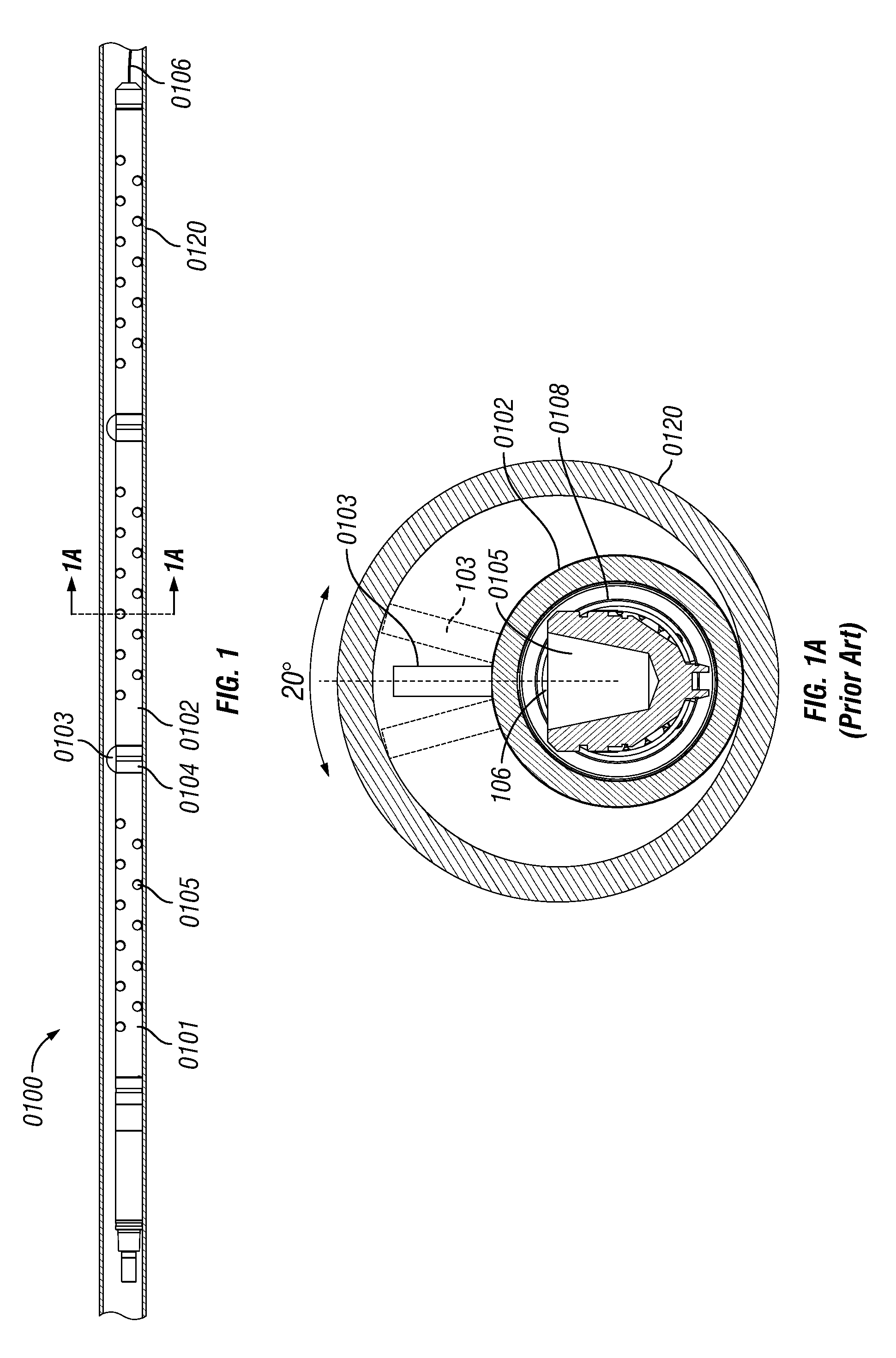
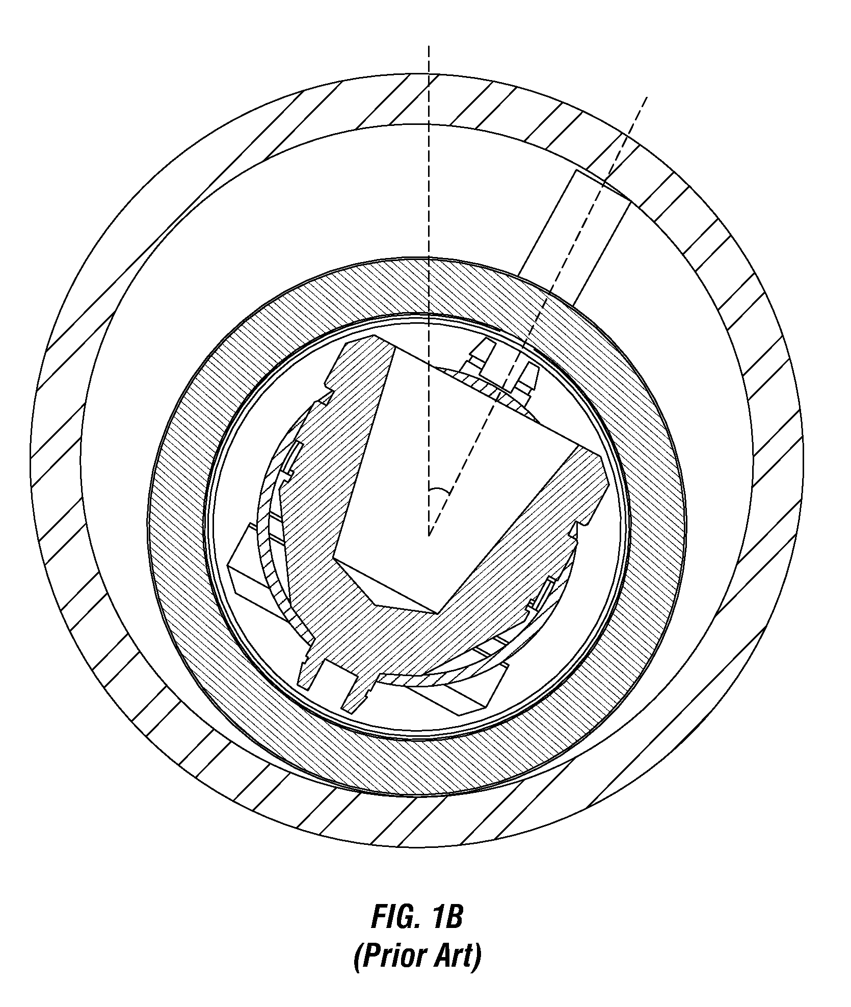
This method has the advantage of being a low cost solution, but the disadvantage of being a less accurate means of orienting the charges.
This method has the advantage of greater accuracy, but can add significant cost to the entire gun assembly, as bearings and rollers are needed to allow rotation of the internal structure with limited available force.
In addition, the bearings and rolling mechanism may fail to turn, either through binding from friction or binding due to thermal expansion, or because the gun may be slightly bent due to variation in the well straightness.
In this case, the charges may shoot in any random direction and result in well performance worse than may have been achieved with conventional spiral phased charges which require no orientation.
The rotating internal components may sever the wire, or require a rotating junction, both of which decrease reliability of the gun system.
Finally, the bearings and weights required for these systems often reduce the maximum possible charge size, and lower gram weight charges may be needed than would be used in a conventional system of equivalent diameter.
The Prior Art as Detailed Above Suffers from the following deficiencies:Prior art systems do not provide for a better than + / −15 degrees accuracy to reduce tortuosity and increase well performance.Prior art systems do not provide for preventing perforation in a random direction used in conventional bearings and roller mechanism.Prior art systems do not provide for maximizing charge size in order to achieve maximum perforation efficiency.Prior art systems do not provide for maximizing the number of charges by using the length of the perforating guns to maximize shot density.Prior art systems do not provide for adjusting to deviations in the wellbore casing or straightness in perforating gun to orient the charges in a desired orientation for perforation.Prior art systems do not provide for a reliable and simple thorough wire to enable select fire systems with external or internal swiveling orienting guns.
While some of the prior art may teach some solutions to several of these problems, the core issue of externally orienting perforating guns with limited internal correction has not been addressed by prior art.

Method used


Image

  • Externally-orientated internally-corrected perforating gun system and method
  • Externally-orientated internally-corrected perforating gun system and method
  • Externally-orientated internally-corrected perforating gun system and method

Examples


Embodiment Construction

[0074]While this invention is susceptible of embodiment in many different forms, there is shown in the drawings and will herein be described in detailed preferred embodiment of the invention with the understanding that the present disclosure is to be considered as an exemplification of the principles of the invention and is not intended to limit the broad aspect of the invention to the embodiment illustrated.

[0075]The numerous innovative teachings of the present application will be described with particular reference to the presently preferred embodiment, wherein these innovative teachings are advantageously applied to the particular problems of an externally oriented perforation gun system and method. However, it should be understood that this embodiment is only one example of the many advantageous uses of the innovative teachings herein. In general, statements made in the specification of the present application do not necessarily limit any of the various claimed inventions. Moreo...


PUM


Abstract

An externally-oriented internally-corrected perforating gun system and method for accurate perforation in a deviated wellbore is disclosed. The system / method includes a gun string assembly (GSA) deployed in a wellbore with an external protuberance member (EPM) and an internal pivot support (IPS). With the EPM oriented to the high side of the wellbore, the center of mass of the GSA positions the GSA at the lower side of the wellbore surface. The IPS is attached to internal gun components such end plate, charge holder tube, detonating cord or charge case. The charges inside the charge holder tube move with the gravitational vector about the IPS and point more accurately in the desired direction for perforating. The external orientation of the EPM along with limited internal swing about the IPS provide for an accurate orientation of the charges that results in efficient and effective perforating through a hydrocarbon formation.

Description

CROSS REFERENCE TO RELATED APPLICATIONS[0001]Not ApplicablePARTIAL WAIVER OF COPYRIGHT[0002]All of the material in this patent application is subject to copyright protection under the copyright laws of the United States and of other countries. As of the first effective filing date of the present application, this material is protected as unpublished material.[0003]However, permission to copy this material is hereby granted to the extent that the copyright owner has no objection to the facsimile reproduction by anyone of the patent documentation or patent disclosure, as it appears in the United States Patent and Trademark Office patent file or records, but otherwise reserves all copyright rights whatsoever.STATEMENT FEDERALLY SPONSORED RESEARCH OR DEVELOPMENT[0004]Not ApplicableREFERENCE TO A MICROFICHE APPENDIX[0005]Not ApplicablePRIOR ART AND BACKGROUND OF THE INVENTION[0006]1. Field of the Invention[0007]The present invention generally relates orienting perforating guns in oil and...

Claims


Application Information

Patent Timeline
Patent Type & Authority Patents(United States)
IPC IPC(8): E21B43/118E21B23/01E21B43/119E21B43/117
CPCE21B43/119E21B43/118E21B23/01E21B43/117
Inventor HARDESTY, JOHN T.CLARK, NATHAN G.ROLLINS, JAMES A.WESSON, DAVID S.
Owner GEODYNAMICS
Why Eureka
Try Eureka