
Electrode plate for plasma etching and plasma etching apparatus

Active Publication Date: 2015-08-25
TOKYO ELECTRON LTD
View PDF47 Cites 10 Cited by
  • Summary
  • Abstract
  • Description
  • Claims
  • Application Information

AI Technical Summary

Benefits of technology

This solution effectively prevents abnormal discharges on the rear surface of the upper electrode, maintains stable process characteristics, and extends the lifespan of the electrode plate by reducing plasma-induced wear and contamination.

Problems solved by technology

For example, in the plasma etching apparatus, it is difficult to exhaust gas on an outer circumferential side of the electrode plate, and thus, the discharge is likely to generate at the outer circumferential portion of the electrode plate.

Method used


Image

  • Electrode plate for plasma etching and plasma etching apparatus
  • Electrode plate for plasma etching and plasma etching apparatus
  • Electrode plate for plasma etching and plasma etching apparatus

Examples


example

Arrangement Example (5)

Arrangement Example Considering Lifespan or Productivity

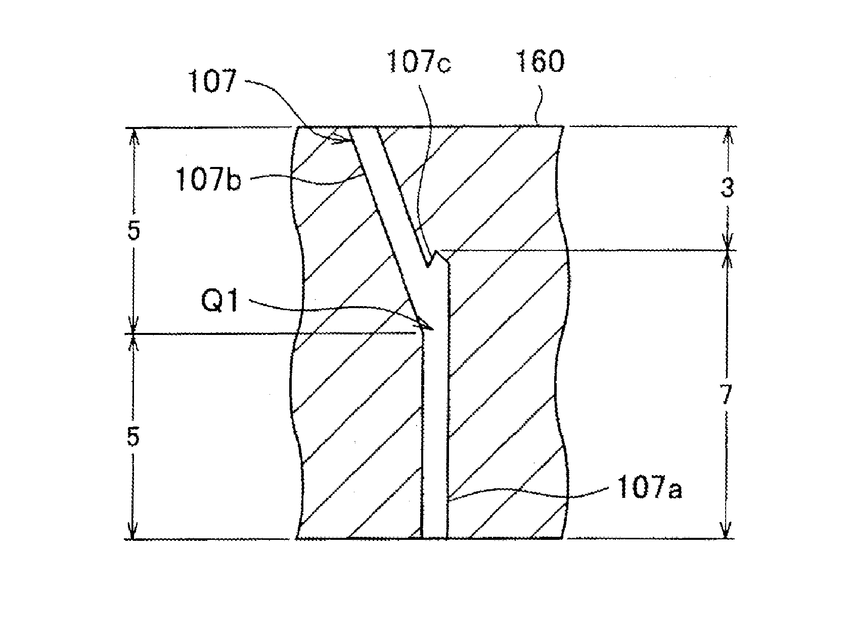
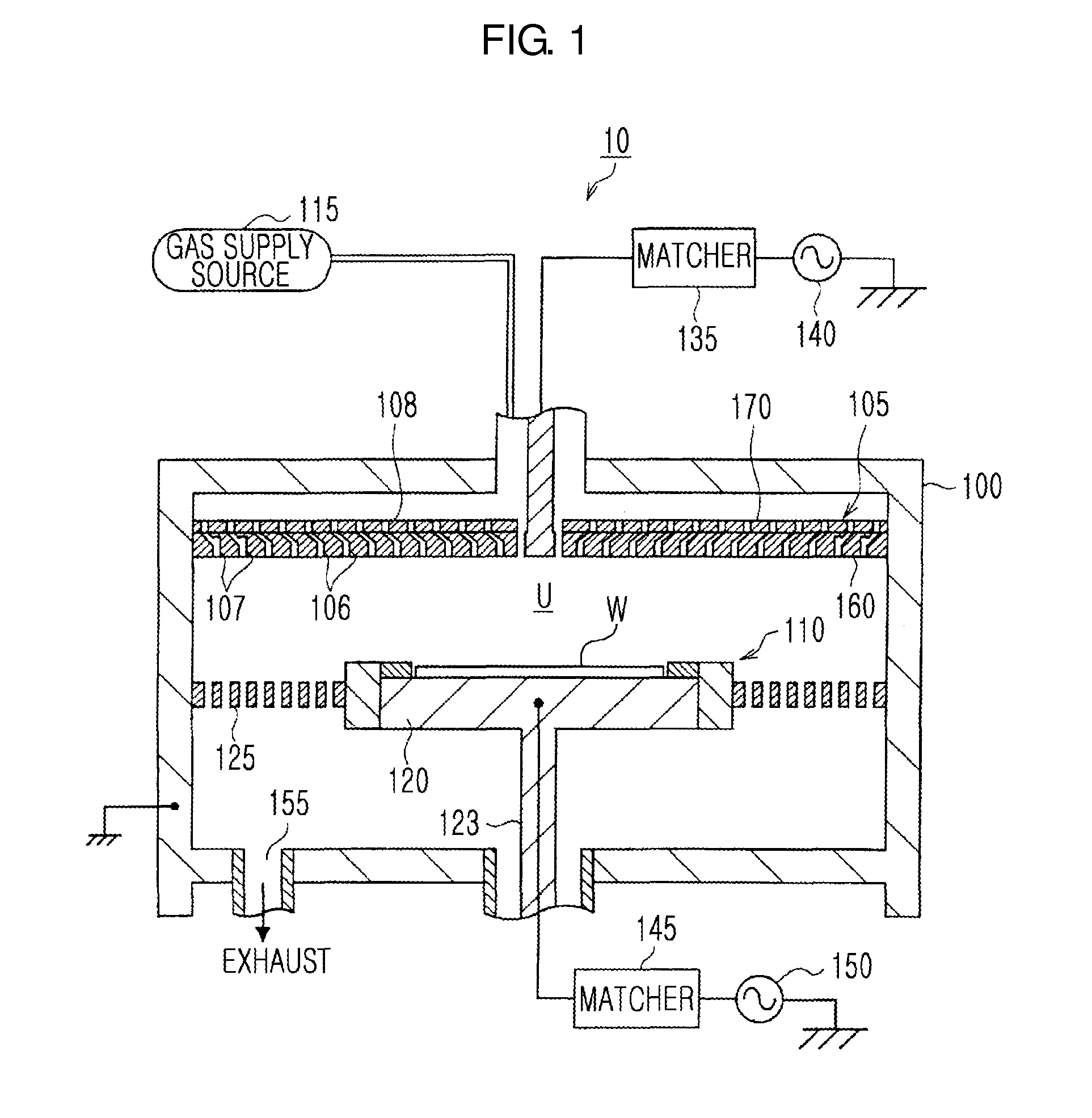
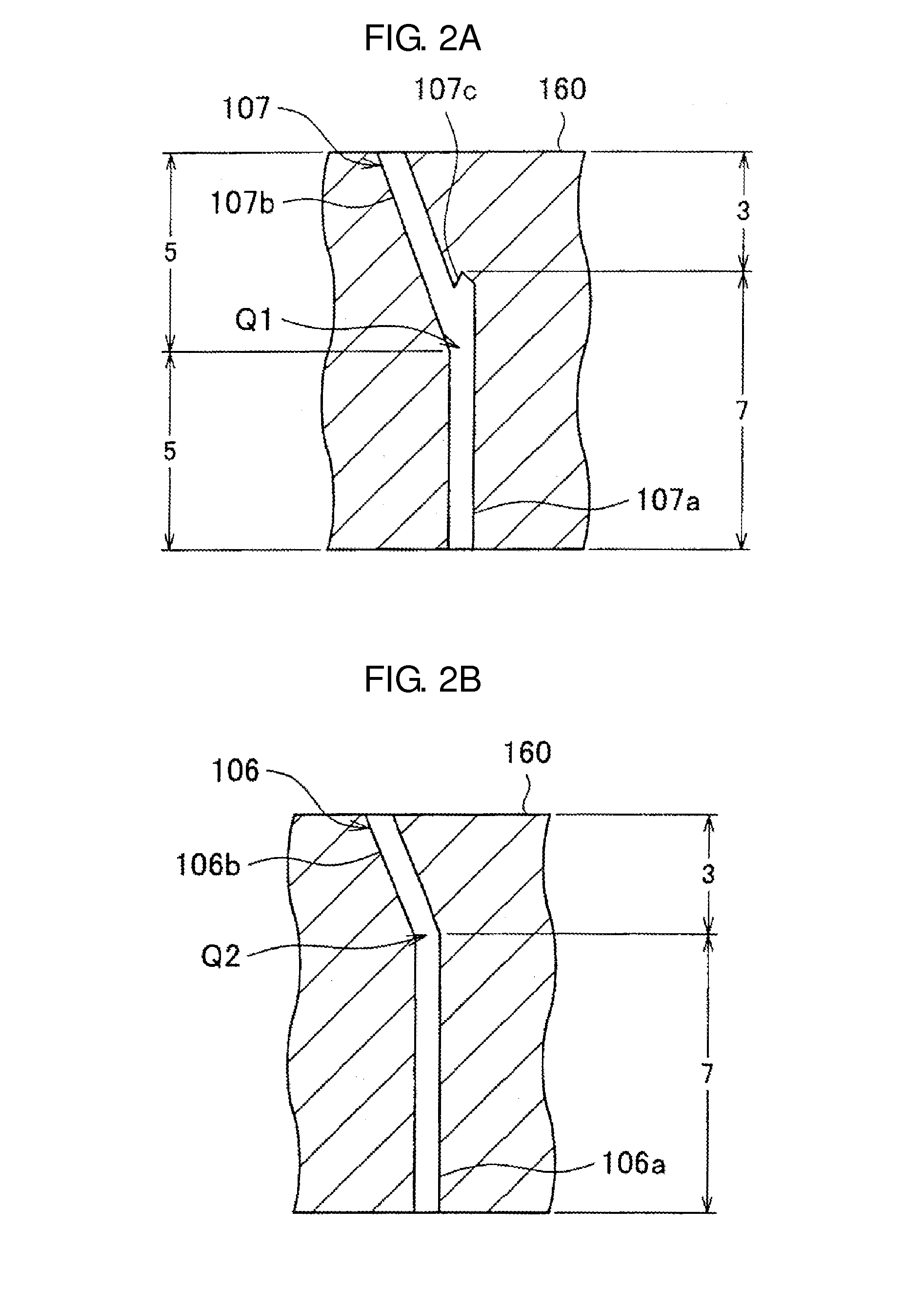
[0091]According to the arrangement example (5), the standard holes are provided in the inner circumferential region, the first inclined holes 106 (7:3) or the standard holes are provided in the intermediate region, and the first inclined holes 106 (7:3) are provided in the outer circumferential region. In the arrangement example (5), the bent holes are provided in the outer circumferential region (and the intermediate region), and thus, the abnormal discharge may be prevented throughout the region where the discharge is most likely to generate. In addition, by providing the standard holes in the inner circumferential region where the discharge hardly generates, the productivity may be improved.

[0092]As described above, the arrangement focusing on preventing the abnormal discharge throughout the region where the discharge is likely to generate and focusing on the amount of abrasion, the productivity, or th...


PUM

PropertyMeasurementUnit
thicknessaaaaaaaaaa
RF poweraaaaaaaaaa
RF poweraaaaaaaaaa

Abstract

An electrode plate for a plasma etching is formed as a disc shape having a predetermined thickness, a plurality of gas holes penetrating a surface of the electrode plate perpendicularly to the surface are provided on different circumferences of a plurality of concentric circles, the electrode plate is divided in a radial direction of the electrode plate into two or more regions, types of gas holes provided in the two or more regions are different from each other by region.

Description

CROSS-REFERENCE TO RELATED PATENT APPLICATIONS[0001]This application claims the benefits of Japanese Patent Application No. 2010-215315, filed on Sep. 27, 2010 in the Japan Patent Office, and U.S. Patent Application No. 61 / 407,650, filed on Oct. 28, 2010 in the U.S. Patent and Trademark Office, the disclosures of which are incorporated herein in its entirety by reference.BACKGROUND OF THE INVENTION[0002]1. Field of the Invention[0003]The present invention relates to an electrode plate for a plasma etching and a plasma etching apparatus, and more particularly, to an arrangement of gas holes in the electrode plate.[0004]2. Description of the Related Art[0005]As an upper electrode of a plasma etching apparatus, an electrode plate (CEL) on a side of a plasma generating space and a cooling plate on an opposite side to the plasma generating space are provided to be adjacent to each other. The electrode plate is a disc-shaped member formed of silicon (Si) to a predetermined thickness, and ...

Claims


Application Information

Patent Timeline
Patent Type & Authority Patents(United States)
IPC IPC(8): C23C16/50C23C16/509C23C16/455C23F1/00C23C16/505C23C16/503H01L21/306H01J37/32C23C16/06C23C16/22
CPCH01J37/32449C23C16/455C23C16/45561C23C16/45563C23C16/45565C23C16/505C23C16/509H01J37/3244H01J37/32541H01J37/32009H01L21/67069
Inventor SATOH, NAOYUKINAGAYAMA, NOBUYUKINAGAKUBO, KEIICHI
Owner TOKYO ELECTRON LTD
Learn More