Cooling arrangement for at least one battery in a vehicle

a technology for cooling arrangements and batteries, applied in battery/fuel cell control arrangements, cell components, electric devices, etc., can solve the problems of battery and regulating equipment being subject to a certain amount of warming, and battery consumption is relatively large, so as to ensure good cooling of the battery and minimal energy consumption

Inactive Publication Date: 2015-08-25
SCANIA CV AB
View PDF15 Cites 2 Cited by
  • Summary
  • Abstract
  • Description
  • Claims
  • Application Information

AI Technical Summary

Benefits of technology

[0006]The object of the present invention is to propose a cooler arrangement which makes it possible for a battery to be situated at substantially any desired external location on a vehicle while at the same time good cooling of the battery is assured with minimal energy consumption.
[0007]This object is achieved with the cooler arrangement of the kind mentioned in the introduction which is characterised by the features herein disclosed. Direct contact of surrounding air with the battery is prevented by the battery being enclosed in a container. The container enclosing the battery may therefore even be situated at locations in the vehicle where the surrounding air contains pollutants and moisture. The container should nevertheless not be situated in the engine space or anywhere else in the vehicle where the air is at a higher temperature than the surroundings, since the cooling effect of the air would thus be reduced. The container therefore also encloses the cooling circuit with the circulating cooling medium. The container thus also prevents surrounding air coming into direct contact with and polluting the cooling medium. In most situations, surrounding air will be at a low enough temperature to provide very good cooling of the circulating cooling medium in the cooling circuit and hence of the battery. Using existing air at the temperature of the surroundings to cool the cooling medium makes it possible, in favourable circumstances, for the cooling medium to provide cooling to a temperature substantially corresponding to the temperature of the surroundings. The container comprises a specific heat release region where the cooling medium is intended to release heat to surrounding air. The configuration of this heat release region is with advantage such that the cooling medium can release heat to surrounding air effectively. The advantage of using surrounding air to cool the cooling medium and hence the battery is that such cooling involves substantially no energy consumption.
[0009]According to an embodiment of the present invention, the cooling circuit comprises a first duct in which the cooling medium comes into contact with an internal surface of the heat release region. The heat transfer between the cooling medium and the internal surface in the heat release region is related inter alia to the flow velocity of the cooling medium in the duct. Said circulation means ensures that the cooling medium always flows at a suitable velocity through the duct. The internal surface may comprise flanges or similar protruding portions of material which extend into the duct. Such portions of material increase the internal surface in the heat release region. A large internal heat transfer surface will result in effective cooling of the cooling medium in the heat release region.
[0010]According to a preferred embodiment of the present invention, the cooler arrangement comprises an air duct for surrounding air in which the air comes into contact with an external surface of the heat release region, and flow means adapted to causing a forced air flow through the air duct. The ability of the surrounding air to cool the external surface is related inter alia to the flow velocity of the air in the duct. Said flow means, which may be a fan, ensures that the air always flows at a suitable velocity through the air duct. Alternatively, or in combination, said flow means may comprise the air duct being so arranged that the vehicle's movement during operation creates an air flow through the air duct. The external surface may comprise flanges or similar portions of material which extend into the air duct, thereby increasing the external surface in the heat release region and hence promoting the heat transfer between the external surface and the air which flows in the air duct.
[0013]According to another preferred embodiment of the invention, the extra cooling element is an evaporator of an AC installation. The refrigerant in an AC installation may reach a very low temperature during the phase transition in the evaporator. This makes it possible to subject the cooling medium to a second step of cooling to a lower temperature than that of the surrounding air. The cooler arrangement may comprise a control unit adapted to deciding whether it is possible to cool the medium to a desired temperature in the ordinary heat release region and, when such is not the case, to activating the cooling element so that it cools the cooling medium in the extra heat release region to the desired temperature before the medium is led to the battery. In this case the surrounding air may be used for an optimum first step of cooling of the cooling medium, while the remaining cooling of the medium is effected by the cooling element in the extra heat release region. Cooling the cooling medium to a lower temperature than that of the surroundings involves energy consumption. In this case surrounding air is therefore used for an optimum first step of cooling of the cooling medium before the cooling element effects a residual second step of cooling. It is thus possible to minimise the second step of cooling and hence minimise the energy consumption involved in cooling the cooling medium.
[0014]According to another embodiment of the present invention, the cooling circuit comprises an alternative duct which has an extent past the ordinary heat release region, and a guide element which is adapted to alternatively leading the circulating cooling medium through the first duct or through the second duct, and the control unit is adapted to controlling said guide element so that the cooling medium is led through the second duct in situations where surrounding air is at too high a temperature to be able to cool the cooling medium in the ordinary heat release region. If the surrounding air is at a higher temperature than the cooling medium, it will warm the cooling medium in the heat release region. To prevent this, when the temperature of the surroundings is too high, the cooling medium is therefore led instead through the second duct. The cooling medium is thus prevented from being warmed by surrounding air in the heat release region. In this case the cooling medium is cooled only by the cooling element in the extra heat release region.

Problems solved by technology

The battery and the regulating equipment are inevitably subject to a certain amount of warming during operation.
Using an AC installation to cool the battery consumes a relatively large amount of energy.

Method used


Image

  • Cooling arrangement for at least one battery in a vehicle
  • Cooling arrangement for at least one battery in a vehicle
  • Cooling arrangement for at least one battery in a vehicle

Examples


Embodiment Construction

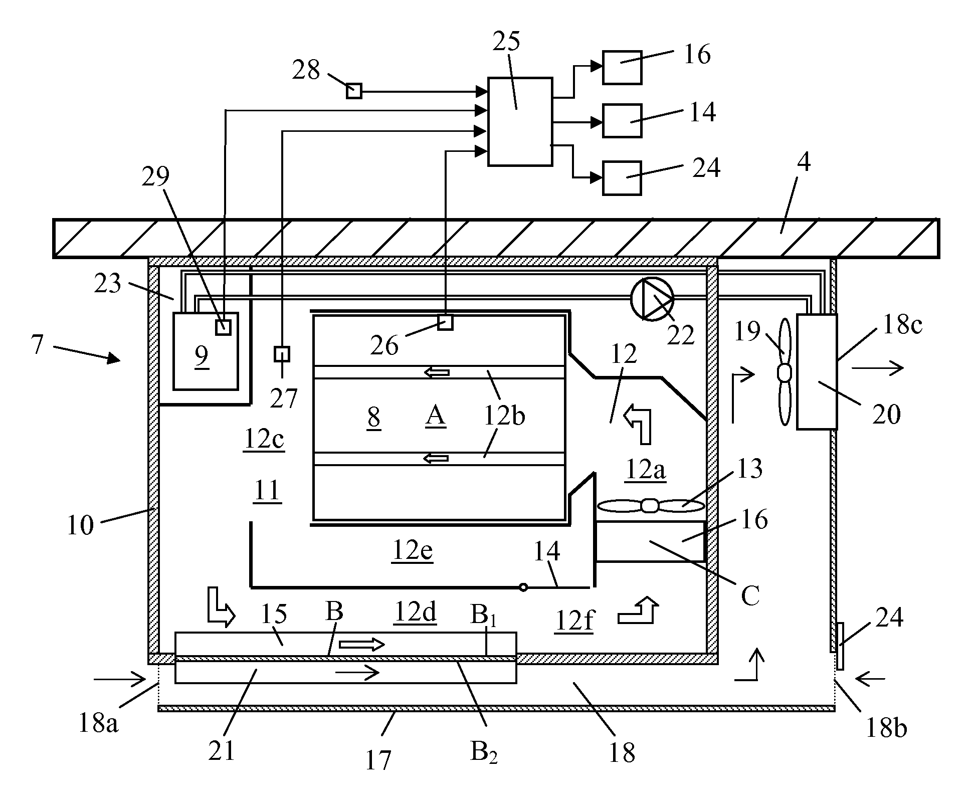
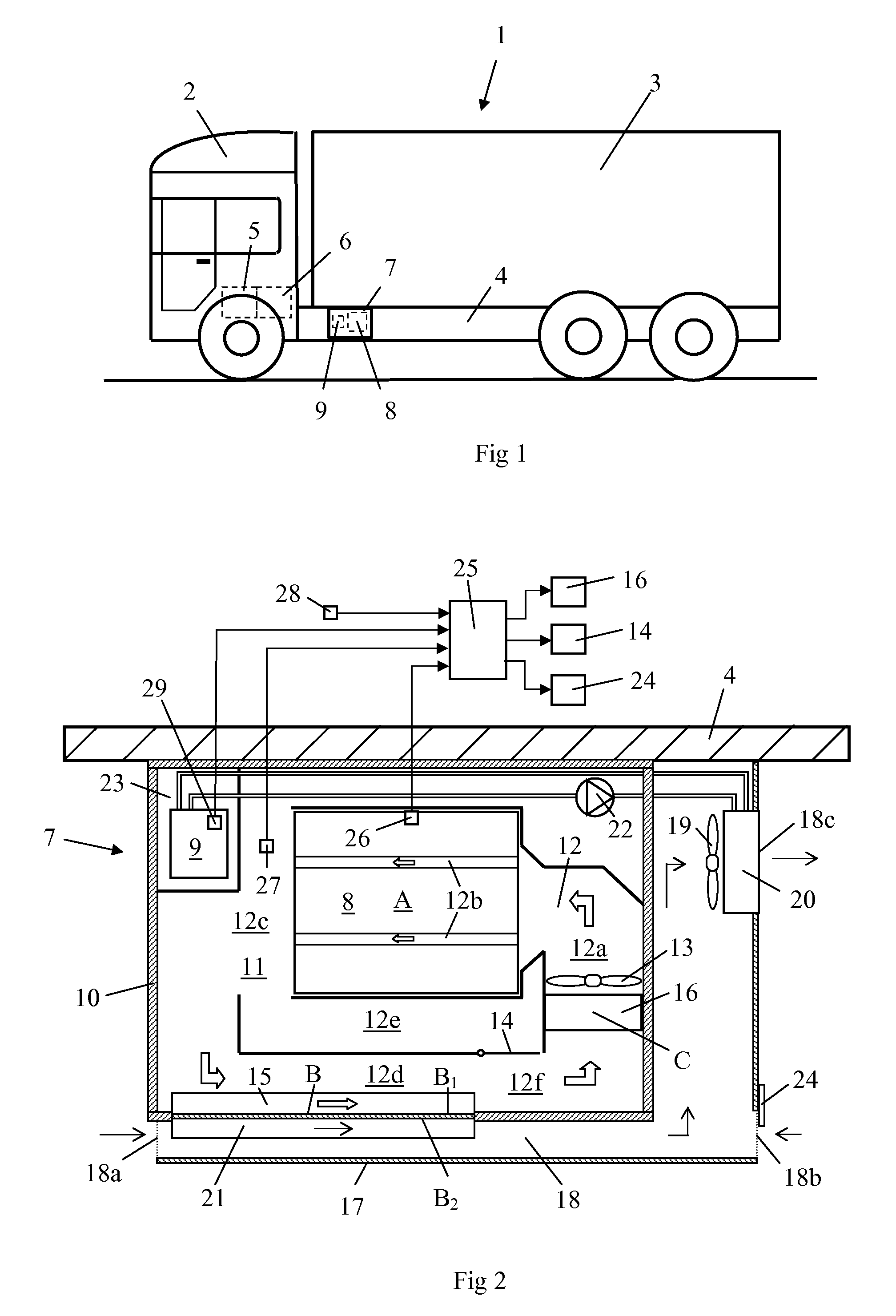
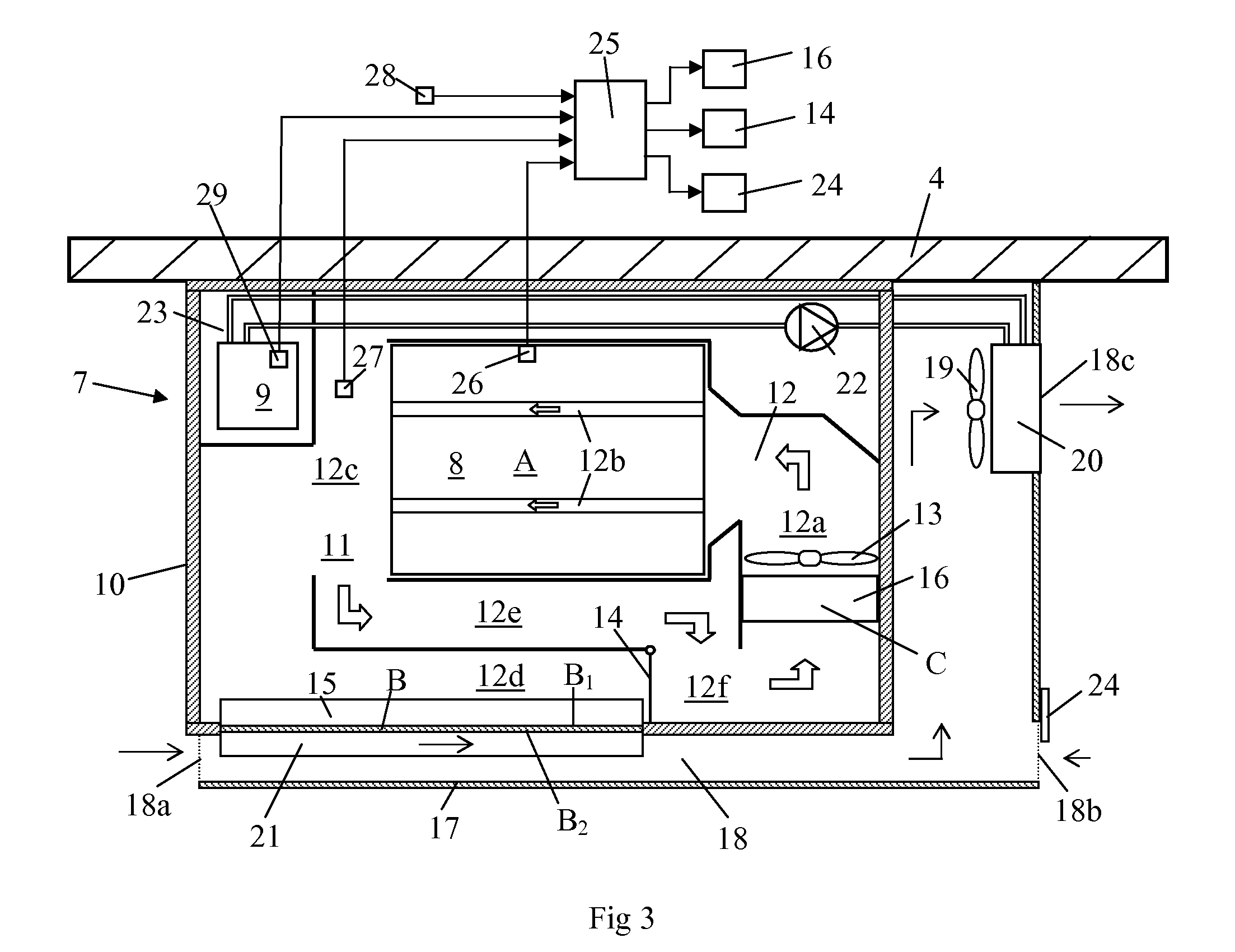
[0020]FIG. 1 depicts a freight vehicle 1 provided with a driver's space 2 and a cargo space 3. The bodywork of the freight vehicle 1 comprises longitudinal loadbearing members 4. The freight vehicle 1 is a hybrid vehicle powered by a schematically depicted combustion engine 5 or by a schematically depicted electrical machine 6. The electrical machine 6 serves as a motor when it powers the vehicle 1 by itself or in conjunction with the combustion engine 5. The electrical machine 6 serves as a generator in situations where the vehicle is being braked, in which case it can itself brake the vehicle up to a certain level of braking. At higher levels of braking the braking process is completed by the vehicle's ordinary brakes. A container device 7 is fastened on one of the loadbearing members 4. A battery 8 for storage of electrical energy and regulating equipment 9 which regulates the flow of electrical energy between the battery 8 and the electrical machine 6 are situated in the contain...


PUM

PropertyMeasurementUnit
temperatureaaaaaaaaaa
temperaturesaaaaaaaaaa

Abstract

A cooler arrangement for at least one battery (8) in a vehicle (1) includes a cooling circuit (12a-f) with a circulating cooling medium, a circulator (13) to circulate the cooling medium in the cooling circuit (12a-f), and a cooling region (A) where the cooling medium cools the battery (8). The cooler arrangement includes a container (10) with an enclosed internal space (11), in which the battery (8) and the cooling circuit (12a-f) with the circulating cooling medium are situated, and the container (10) includes a heat release region (B) where cooling medium is intended to release heat to surrounding air.

Description

CROSS-REFERENCE TO RELATED APPLICATIONS[0001]The present application is a 35 U.S.C. §§371 national phase conversion of PCT / SE2010 / 051271, filed Nov. 18, 2010 which claims priority of Swedish Application No. 0950883-9, filed Nov. 20, 2009, the contents of which are incorporated by reference herein. The PCT International Application was published in the English language.BACKGROUND TO THE INVENTION AND PRIOR ART[0002]The present invention relates to a cooler arrangement for at least one battery in a vehicle.[0003]Hybrid vehicles powered by electricity in combination with some other form of fuel are equipped with one or more batteries for storage of electrical energy and with regulating equipment for regulating the flow of electrical energy between the battery and an electrical machine which alternately serves as motor or generator, depending on the vehicle's operating state. The battery and the regulating equipment are inevitably subject to a certain amount of warming during operation....

Claims


Application Information

Patent Timeline
Patent Type & Authority Patents(United States)
IPC IPC(8): H02J7/00B60L11/18B60L3/00H01M10/613H01M10/6568H01M10/6563H01M10/625H01M10/63H01M2/10H01M50/202H01M50/249
CPCH01M10/625B60L3/0046B60L11/1874B60L11/1877H01M2/1077H01M10/6568H01M10/6563H01M10/63H01M10/613B60L2240/36Y02T10/705Y02T10/7005B60L58/26B60L50/66Y02T10/70Y02E60/10H01M50/249B60L50/64H01M50/202H01M10/60B60H1/00278
Inventor TSYCHKOV, ALEXEIKOLASA, MAGNUS
Owner SCANIA CV AB
Why Eureka
Try Eureka