Operating a controller for an energy production plant

a technology for energy production plants and controllers, applied in the field of operating controllers for energy production plants, can solve the problems of affecting the normal operation of the controller and/or the entire energy production plant, unable to provide reference signals, etc., and achieve the effect of preventing deterioration of the stability of the components and in particular the stability of the grid, and preventing damage to the components

Inactive Publication Date: 2015-08-25
SIEMENS AG
View PDF7 Cites 4 Cited by
  • Summary
  • Abstract
  • Description
  • Claims
  • Application Information

AI Technical Summary

Benefits of technology

[0014]By smoothly approaching the desired value starting from the actual value of the electrical quantity the stability of the grid may be improved.
[0018]Temporally varying the plural reference signals may be performed across a time interval between 10 s and 120 s, in particular between 10 s and 60 s for example. Thereby, a cautious approaching from the actual value to the desired value may be achieved, in particular avoiding (or at least reducing) jump-like changes of the reference signals. By avoiding jump-like changes (or at least reducing their step size) of the reference signals also the operation of the wind turbine may be improved, since a jump-like change of the reference signal supplied the wind turbine may cause excitation of several oscillation modes in electrical and / or mechanical components of the wind turbine, such as within the converter, within the generator and / or within the rotation shaft of the wind turbine at which plural rotor blades are connected.
[0026]The predetermined time interval may be considerably larger than the normal operation time interval within which the desired value received is utilized in order to generate the plural reference signals to be sent to the wind turbines. Thereby, smoothly approaching the desired value starting from the actual value may be achieved, in particular avoiding at least some of the oscillations occurring in conventional systems or controllers.
[0028]Thereby, it may be avoided that the intermediate value equals to the desired value within the first half of the predetermined time interval, in order to reduce excitation of oscillations.
[0044]The grid operator may define properties of the grid and may derive therefrom the second signal which may be communicated to the controller of the energy production plant. The grid operator may for example define a voltage level, a reactive power, a power factor and an active power at the point of common coupling. The controller of the energy production plant may in turn be responsible to operate the wind turbines such that the electrical properties as set by the grid operator are achieved at the common node without deteriorating stability of the components and in particular the stability of the grid and without hampering or damaging the component of the energy production plant.

Problems solved by technology

The failure may in particular be related to a failure of the controller itself and / or to a failure of communication between the controller and other equipment of the energy production plant or a grid operator.
In particular, during the failure the controller may be unable to provide reference signals to the wind turbines which comply to requirements set by a grid operator, since either the controller may not be able to receive respective communication signals from the grid operator or the controller may not be able to receive information regarding the electrical properties at the point of common coupling.
Other failures may occur which may hamper a normal operation of the controller and / or the entire energy production plant.

Method used


Image

  • Operating a controller for an energy production plant
  • Operating a controller for an energy production plant
  • Operating a controller for an energy production plant

Examples


Embodiment Construction

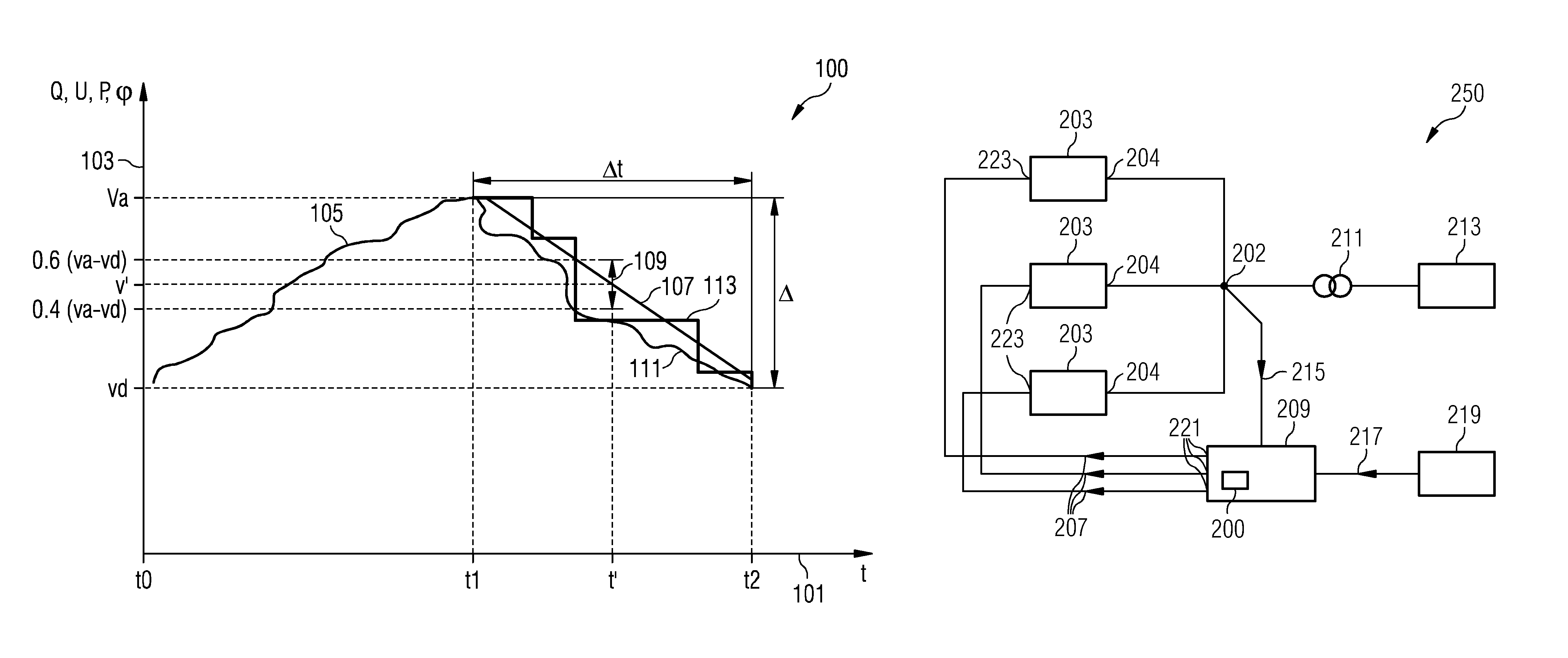
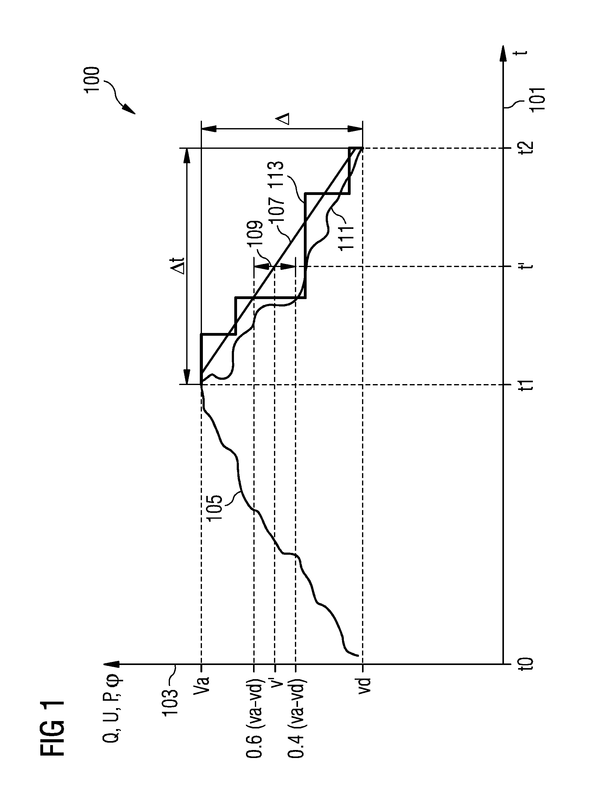
[0059]FIG. 1 illustrates a graph considered in a method of operating a controller according to an embodiment of the present invention. On an abscissa 101 the time t is indicated, while on an ordinate 103 the reactive power Q, the voltage U, the active power P, or the power factor φ or cos(φ) are indicated. The method may be applied for controlling the reactive power Q and / or the voltage U and / or the active power P and / or the power factor φ. At a time point t0 a failure occurs, while the desired value, of e.g. the reactive power, vd is received as a signal (signal 217 in FIG. 2), e.g. from a grid operator (such as grid operator 219 in FIG. 2). The failure takes place between the time points t0 and t1. During the time interval between t0 and t1 the actual value (such as measured at the common node 202 in FIG. 2) changes according to the curve 105 which reaches the actual value va at the first time point t1. In particular, the actual value va may be received from a measurement equipmen...


PUM


Abstract

A method is provided for operating a controller controlling an energy production plant including plural wind turbines each having an electrical output terminal connected to a common node. The method involves determining that a failure relating to the energy production plant has been overcome; receiving a first signal indicative of an actual value of an electrical quantity at the common node; receiving a second signal relating to a desired value of the electrical quantity at the common node; generating plural reference signals based on an intermediate value between the actual value and the desired value; and supplying the reference signals to the wind turbines, the reference signals controlling the wind turbines with respect to their electrical output at the output terminal such that the intermediate value of the electrical quantity at the common node is achieved.

Description

FIELD OF INVENTION[0001]The present invention relates to a method and to an arrangement of operating a controller controlling an energy production plant comprising plural wind turbines, wherein in particular a situation of recovery from a failure is addressed.BACKGROUND OF INVENTION[0002]During an operation of a wind energy production plant or wind park, situations or circumstances may occur where a central plant controller (in particular a controller controlling plural wind turbines comprised in the wind power plant) may have failed or where at least some essential communication(s) between the central plant controller and other equipment, such as measurement equipment or a grid operator, may have failed. In particular, it may be needed to (re)boot up the central plant controller after the failure is overcome.[0003]The plural wind turbines may be connected to a point of common coupling or point of interconnection or common node. In a situation of a failure it may occur that during t...

Claims


Application Information

Patent Timeline
Patent Type & Authority Patents(United States)
IPC IPC(8): F03D9/00H02J3/38
CPCH02J3/386F03D9/005Y02E10/72F03D9/257H02J2300/28H02J3/381Y02E10/76Y02P80/10H02J3/48H02J3/472H02J3/50
Inventor NIELSEN, KAJ SKOV
Owner SIEMENS AG
Why Eureka
Try Eureka