Pedicle drill guide for spinal surgery

a drill guide and pedicle screw technology, applied in bone drill guides, surgery, medical science, etc., can solve the problems of reducing obviating the need to place instruments within the spinal canal, and having inherent risk of neurologic injury, so as to reduce the potential of crushing artifacts

Inactive Publication Date: 2015-09-01
AMENDIA
View PDF27 Cites 22 Cited by
  • Summary
  • Abstract
  • Description
  • Claims
  • Application Information

AI Technical Summary

Benefits of technology

[0011]The guide body is rotatable about the stabilizing anchor pin to allow positioning and alignment of a satellite hole relative to the pedicle. The central stabilizing pin and rotating guide allows the surgeon to fix the medial-lateral position of the guide over the center or lateral center of the pedicle on the AP view while allowing for alignment of the pedicle central axis on the lateral view by rotating the guide body. The guide body has at least 2 satellite holes, preferably at least 3 satellite holes, most preferably 4. The plurality of satellite holes are spaced in 1 mm increments from the center hole. The first satellite hole is at 1 mm distance (d1), a second satellite hole at 2 mm distance (d2), a third satellite hole if used is at 3 mm distance (d3) and a fourth satellite hole if used at 4 mm distance (d4).
[0017]The Jamshidi needle is a cylindrical needle with a tapered cutting tip. The tapered end reduces the potential of crush artifact.

Problems solved by technology

First, pedicle screw instrumentation obviates the need to place instrumentation within the spinal canal with its inherent risk of neurologic injury.
The benefit of pedicle screws in the thoracic spine has been tempered by the potential for catastrophic neurological or soft tissue injuries due to the close proximity of these structures.
The narrow and inconsistent shape of the thoracic pedicles, especially in spinal deformity, makes their placement technically challenging.
Castillo, et al noted, “Another drawback of the pedicle screw implant procedure is that the patient, surgeon, and medical staff are exposed to deleterious amounts of radiation, more specifically those deleterious amounts of radiation associated with fluoroscopy during the pedicle screw implant procedure.
However, studies with cadavers have shown that the surgeon's hands are still at a high risk of radiation exposure.
This prior art punch device while a step forward still was greatly limited in screw placement optimization.

Method used


Image

  • Pedicle drill guide for spinal surgery
  • Pedicle drill guide for spinal surgery
  • Pedicle drill guide for spinal surgery

Examples


Embodiment Construction

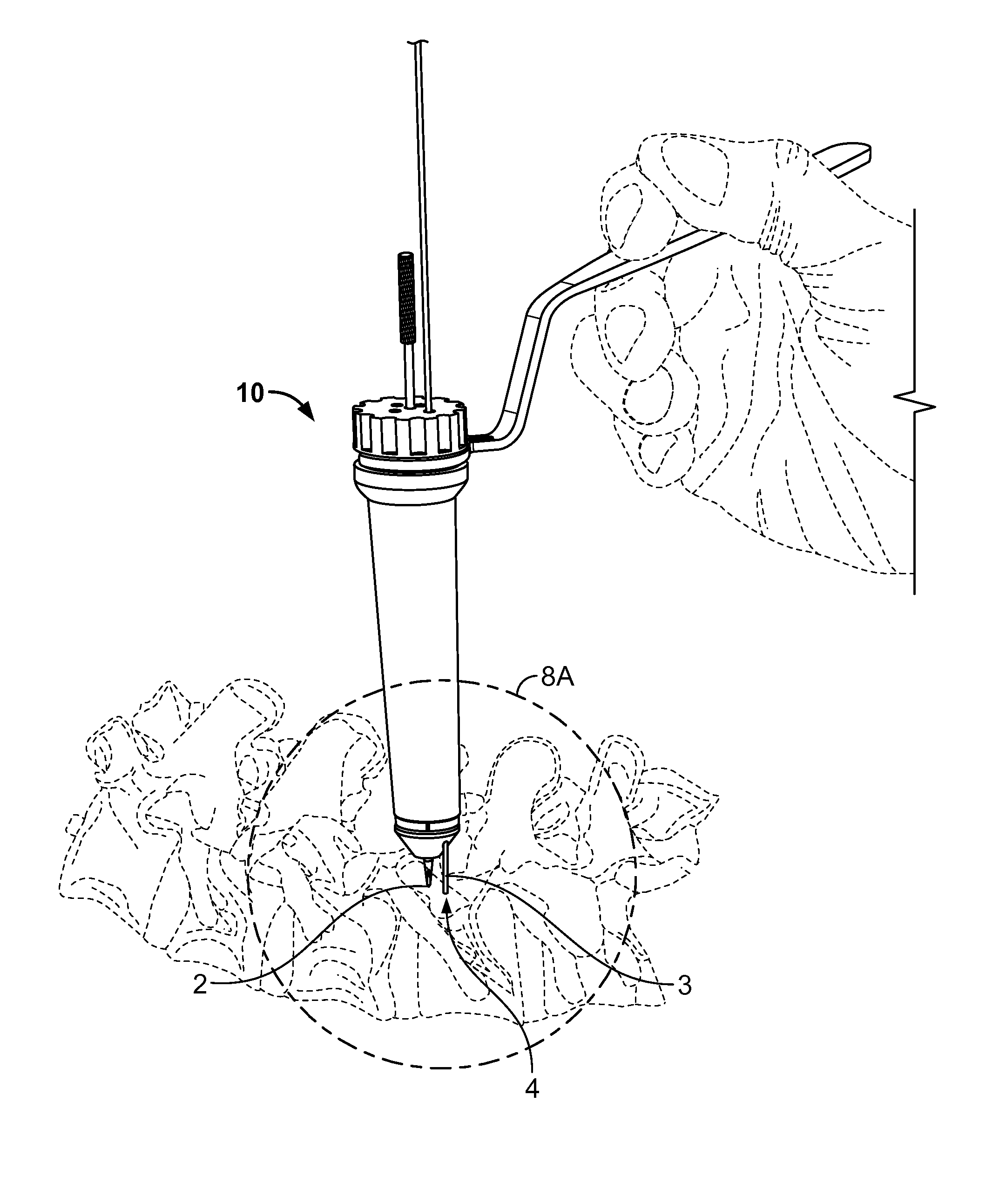
[0040]With reference to FIG. 5, an exploded view of the Pedicle Drill Guide 10 make according to the present invention is shown. The guide device uses three main components, a radiolucent guide body 20, a handle 40 and a stabilizing anchor pin 50. Additionally, a radiopaque image marker or target ring 18 is provided that fits onto a slotted groove 28 on the guide body 20 near an inner tip end 22.

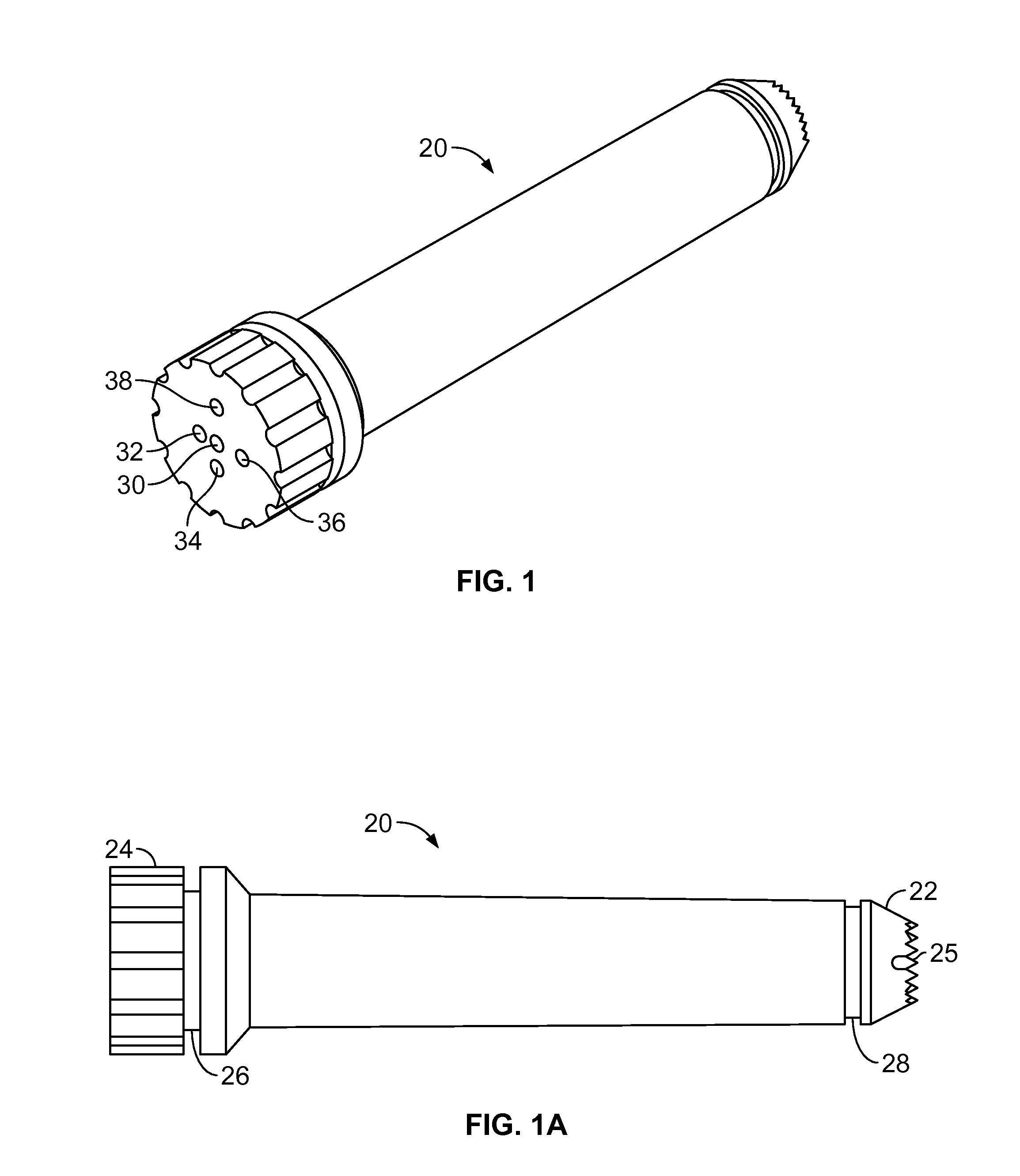
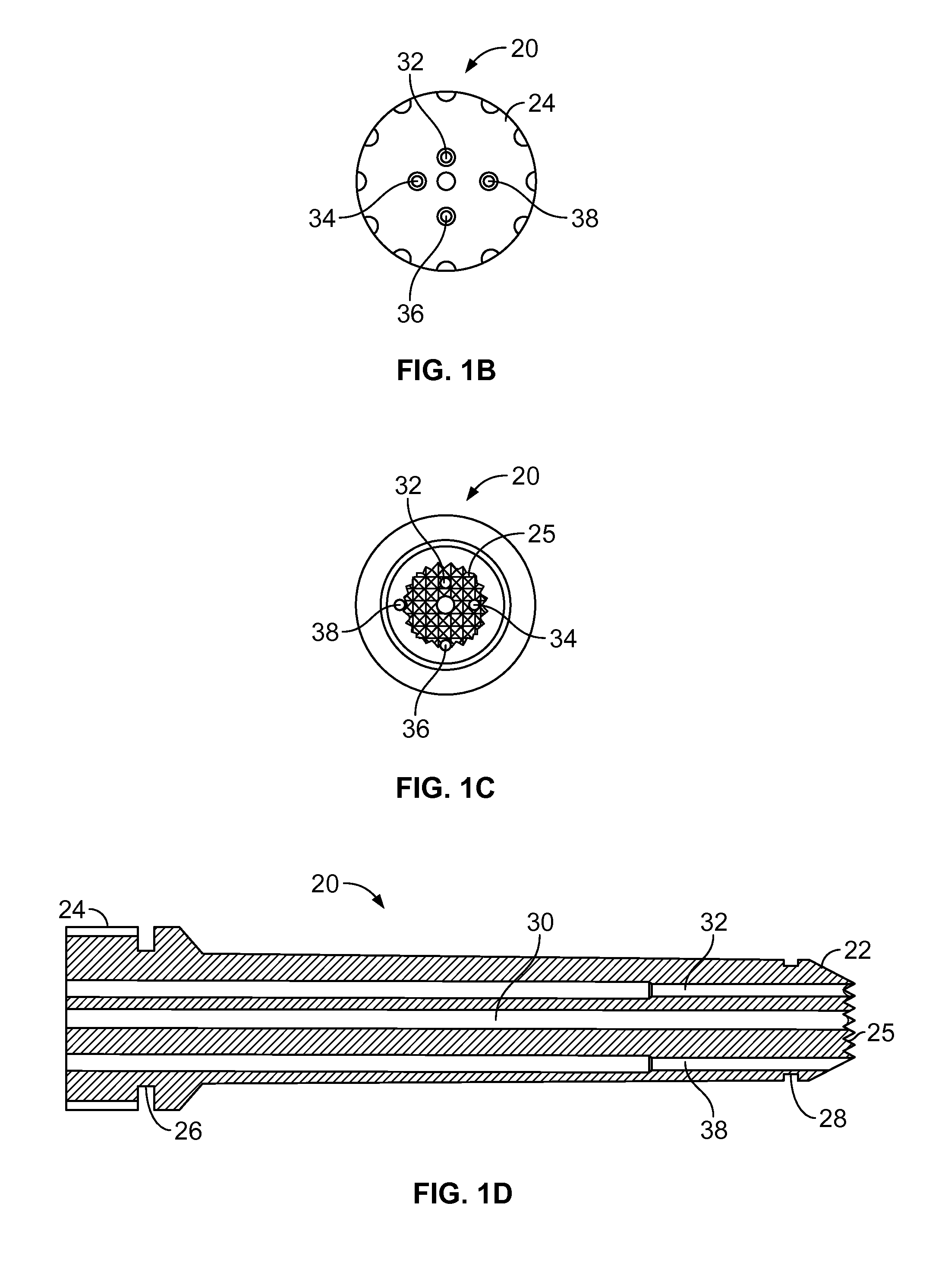
[0041]With reference to FIGS. 1, 1A, 1B, 1C and 1D various views of the guide body 20 are shown. In FIGS. 1, 1A and 1B the enlarged outer end 24 is shown. The enlarged outer end 24 has a knurled or notched surface to facilitate rotation of the guide body 20. The end of the outer end 24 of the guide body 20 shows a center hole 30. This center hole 30 is centered in the guide body 20 and extends through the outer end 24 along the guide body's 20 longitudinal length through the inner tip end 22. The hole 30 forms an axial shaft into which the stabilizing anchor pin 50 fits. The entire guide bod...


PUM


Abstract

A Pedicle Drill Guide is a radiolucent device which allows preliminary positioning of a needle / trochar near the pedicle in the AP view and adjusting the final position of the lateral view without changing the initial position of the AP position. This guide allows simultaneous alignment of both AP and Lateral views for ultimate ideal or perfect pathway for the pedicle cannulization.

Description

RELATED APPLICATIONS[0001]The present application claims priority to U.S. Provisional Application 61 / 468,310 filed Mar. 28, 2011 entitled, “This is a surgical drill guide that is used to cannulate a vertebral pedicle for spinal surgery”.FIELD OF THE INVENTION[0002]The present invention relates to a surgical drill guide that is used to cannulate a vertebral pedicle for spinal surgery.BACKGROUND OF THE INVENTION[0003]Pedicle screw implementation in the spine is a preferred way to provide superior anchorage. Improved deformity correction and overall construct rigidity are two important advantages of pedicle screw instrumentation due its three-column control over the spinal elements. First, pedicle screw instrumentation obviates the need to place instrumentation within the spinal canal with its inherent risk of neurologic injury. Second, the placement of pedicle screws is independent of facet or laminar integrity and thus has been extremely useful in traumatic, neoplastic, and degenerat...

Claims


Application Information

Patent Timeline
Patent Type & Authority Patents(United States)
IPC IPC(8): A61B17/17A61B17/00A61B17/88
CPCA61B17/1757A61B17/8897A61B2017/0046
Inventor MCBRIDE, GEORGE GRADY
Owner AMENDIA
Why Eureka
Try Eureka