

Spinning machine comprising a compaction device
a technology of compaction device and spinning machine, which is applied in the direction of drafting machines, textiles and papermaking, yarn, etc., can solve the problems of inflexible and time-consuming retrofitting, inability to mount and install such a retrofitting unit, and the desire to dismantle to a standard drafting system without a compaction device is in turn very time-consuming and inflexible, so as to achieve simple and quick assembly and disassembly of a comp
- Summary
- Abstract
- Description
- Claims
- Application Information
AI Technical Summary
Benefits of technology
Problems solved by technology
Method used
Image

Examples
Embodiment Construction
[0035]Reference is now made to particular embodiments of the invention, one or more examples of which are illustrated in the drawings. Each embodiment is provided by way of explanation of the invention, and not as a limitation of the invention. For example, features illustrated as described as part of one embodiment may be used with another embodiment to yield still a further embodiment. It is intended that the present invention include these and other modifications and variations.
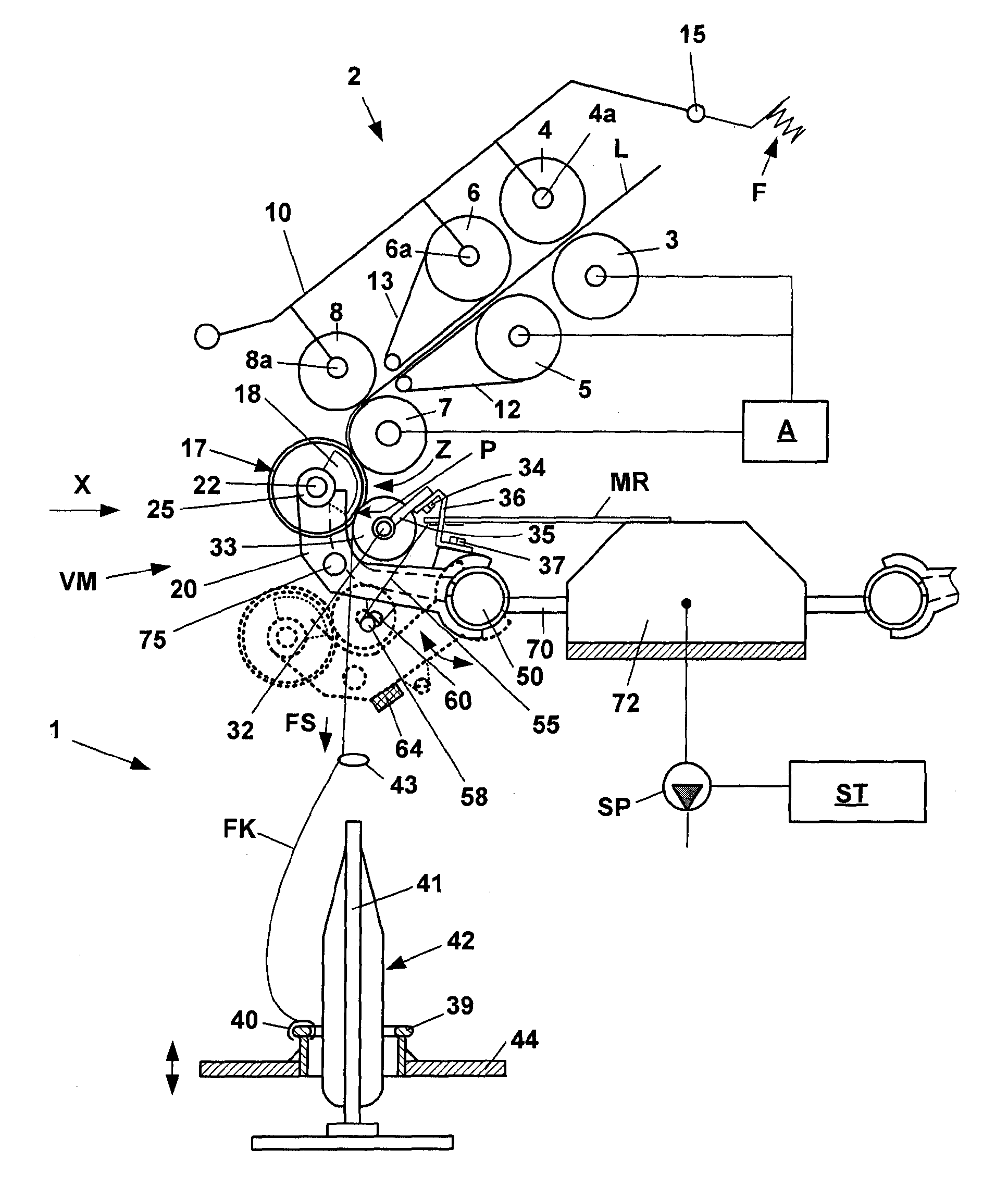
[0036]FIG. 1 shows a schematic side view of a spinning station 1 of a spinning machine (ring spinning machine), having a drafting system unit 2 that is provided with a pair of feed rollers 3, 4, a pair of middle rollers 5, 6, and a pair of delivery rollers 7, 8. An apron 12, 13 is guided around the middle rollers 5, 6, respectively, each of which is held in its illustrated position around a cage, not shown in greater detail. The upper rollers 4, 6, 8 of the mentioned roller pairs are designed as pressure r...
PUM
 Abstract
Description
Claims
Application Information