Non-contact stress measuring device

a non-contact, stress-strain technology, applied in the direction of force measurement by measuring magnetic property varation, instruments, material analysis, etc., can solve the problem of not allowing the direction or magnitude of strain or stress in a component to be resolved

Active Publication Date: 2015-09-08
PRATT & WHITNEY CANADA CORP
View PDF15 Cites 21 Cited by
  • Summary
  • Abstract
  • Description
  • Claims
  • Application Information

AI Technical Summary

Problems solved by technology

However, these methods do not allow for either the direction or magnitude of strain or stress in a component to be resolved.

Method used


Image

  • Non-contact stress measuring device
  • Non-contact stress measuring device
  • Non-contact stress measuring device

Examples


Embodiment Construction

[0025]Various aspects of preferred embodiments are described through reference to the drawings.

[0026]As will be understood by those skilled in the relevant arts, stresses and strains in deformable materials are in general inseparably associated with each other. In many cases they are related to each other according to known relationships, such as through Young's modulus. Thus the measurement of stresses and strains is often physically equivalent, or strongly related. For example, measurement of a strain in an object is equivalent, or strongly related, to determination of stresses. Discussion herein is cast generally in terms of stress, but should be interpreted and understood as applying to both stress and strain, as applicable, accordingly.

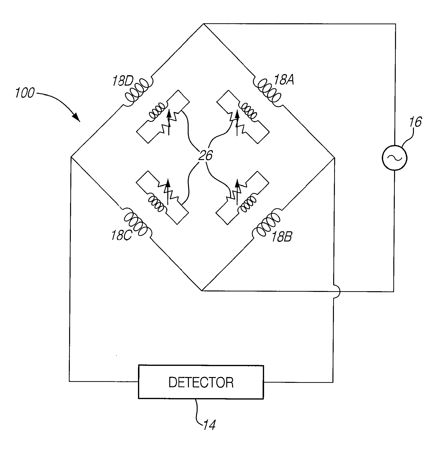
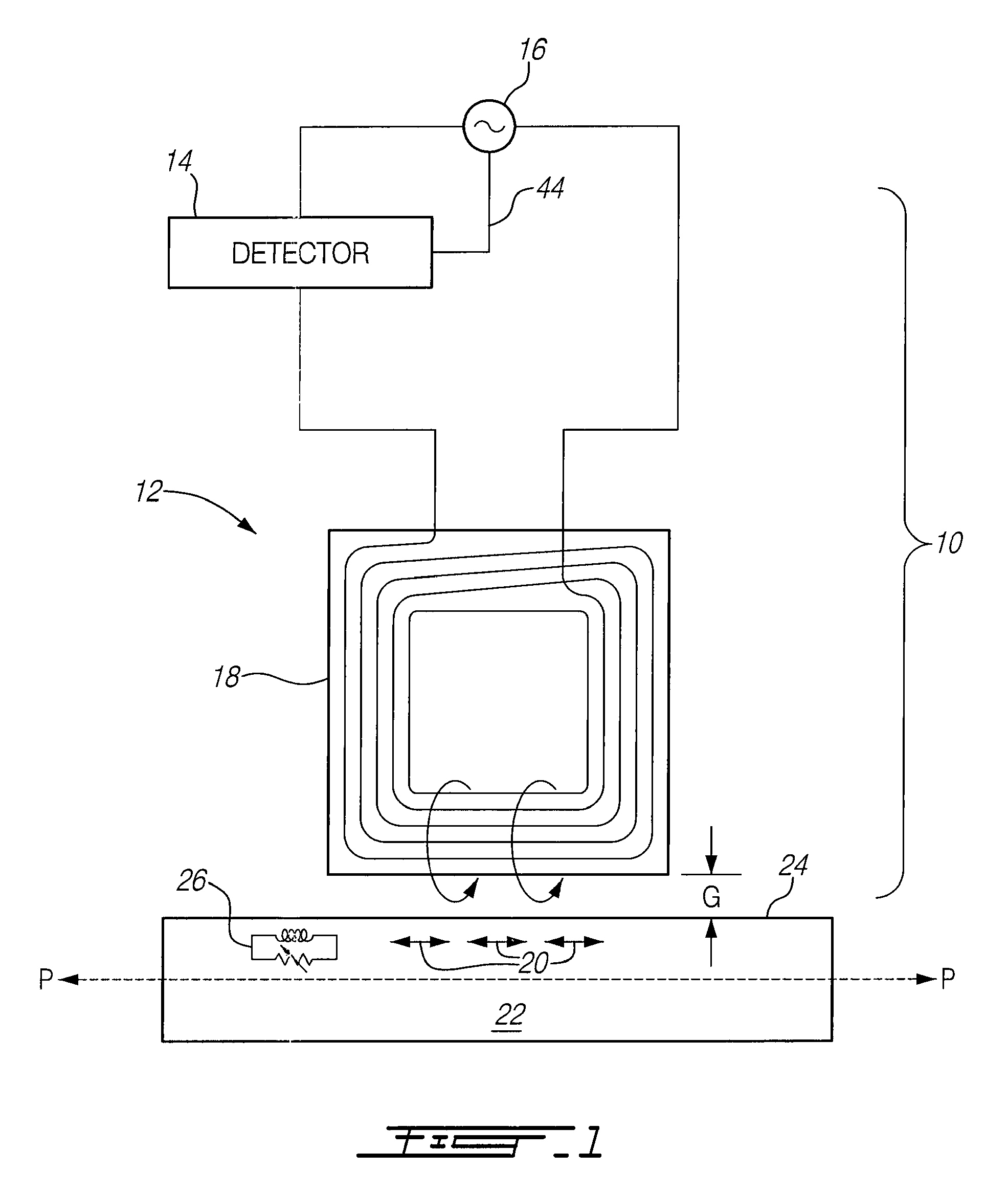
[0027]FIG. 1 shows a stress measuring device 10 that may be used for measuring stress (and / or strain) in a particular direction or along a particular path in an electrically conductive material such as a component 22 without physical contact with...


PUM

PropertyMeasurementUnit
stress/strainaaaaaaaaaa
stressaaaaaaaaaa
alternating currentaaaaaaaaaa

Abstract

Apparatuses and methods for measuring stress or strain in a conductive material without physical contact with the material are provided. The device comprises an inductor circuit configured to induce an alternating current into the material along a first path; and a detector configured to detect a signal representative of the stress in the material along the first path when current is induced in the material.

Description

TECHNICAL FIELD[0001]The disclosure relates to methods and apparatus for measuring stress and strain in electrically conductive materials.BACKGROUND OF THE ART[0002]Non-destructive inspection of materials using eddy currents are known. Such methods may be used to detect flaws such as cracks in components. Some methods make use of flat spiral-shaped induction coils to detect the presence of residual stresses in a material. However, these methods do not allow for either the direction or magnitude of strain or stress in a component to be resolved.[0003]Improvement in non-contact stress / strain measurement methods is therefore desirable, for these and other reasons.SUMMARY[0004]The disclosure describes apparatuses, systems, devices, and processes for measuring stress and strain in electrically conductive materials.[0005]In various aspects, for example, the disclosure describes apparatuses, systems, devices, and processes for measuring stress in conductive material without physically cont...

Claims


Application Information

Patent Timeline
Patent Type & Authority Patents(United States)
IPC IPC(8): G01R27/28G01N27/90G01N3/06G01L1/12G01L3/10G01R27/26
CPCG01N27/90G01L1/127G01L3/105G01N3/066G01R27/2611G01N2203/0075
Inventor DOOLEY, KEVIN ALLAN
Owner PRATT & WHITNEY CANADA CORP
Why Eureka
Try Eureka