Mesh generation system

a technology mesh generation, applied in the field of computer aided engineering system, can solve the problems of difficult decision-making, difficult for a person skilled in analysis to determine the appropriate mesh size in consideration of this controlled mesh size density, and need a lot of time and effort to create a mesh model. the burden of mesh creation can be reduced, and the calculation time is minimal

Inactive Publication Date: 2015-09-08
HITACHI LTD
View PDF7 Cites 2 Cited by
  • Summary
  • Abstract
  • Description
  • Claims
  • Application Information

AI Technical Summary

Benefits of technology

[0013]In view of the foregoing, an object of the invention is to provide a mesh generation system capable of generating a mesh model that can be analyzed with sufficient analysis accuracy for result evaluation and within a minimum possible calculation time, even if the user does not grasp the tradeoff relation between analysis accuracy and analysis time due to mesh size.
[0016]According to the invention, a mesh generation system capable of generating a mesh model that can be analyzed with sufficient analysis accuracy for result evaluation and within a minimum possible calculation time, even if the user does not grasp the tradeoff relation between analysis accuracy and analysis time due to mesh size, can be provided. Therefore, the burden of mesh creation can be reduced.

Problems solved by technology

In the generation of an analysis model in CAE as described above, first, the work of creating a mesh model from a shape model and setting boundary conditions or the like on each element of the mesh model is required, and a lot of time and effort is needed particularly to create a mesh model.
On the other hand, a beginner of analysis needs many trials and errors in order to decide an appropriate mesh size.
Deciding an appropriate mesh size in consideration of this controlled mesh size density is not easy even to a person skilled in analysis.
As described above, CAE has the problem that the burden of mesh creation needs to be reduced.
However, in these techniques, since repetition of arithmetic operations to adjust the degree of an element or the mesh size takes place, there is a problem that the analysis calculation time per analysis is long.
However, when an analysis is carried out tens to hundreds of times in order to find out design sensitivity or for optimized calculation or the like, there is a problem that the approximately five times longer calculation time is longer than the time for trial and error of mesh size.
However, this technique only creates a mesh with relatively high analysis accuracy.
Therefore, there is a problem that the technique does not create a mesh with sufficient accuracy guaranteed.
Therefore, when an analysis is carried out tens to hundreds of times, there is a problem that the calculation time needs to be shortened.
The technique of JP-A-2006-4259 has a problem that the user needs to prepare a mesh with accuracy guaranteed in advance.

Method used


Image

  • Mesh generation system
  • Mesh generation system
  • Mesh generation system

Examples


embodiment 1

Example of Configuration of Mesh Generation System

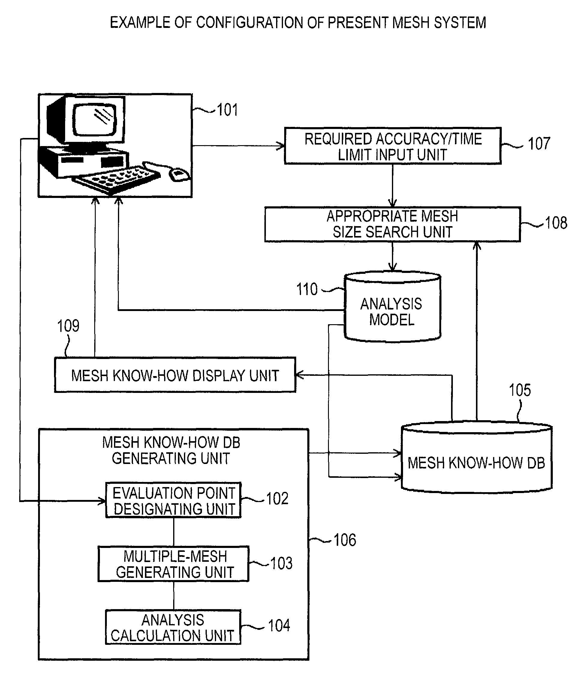
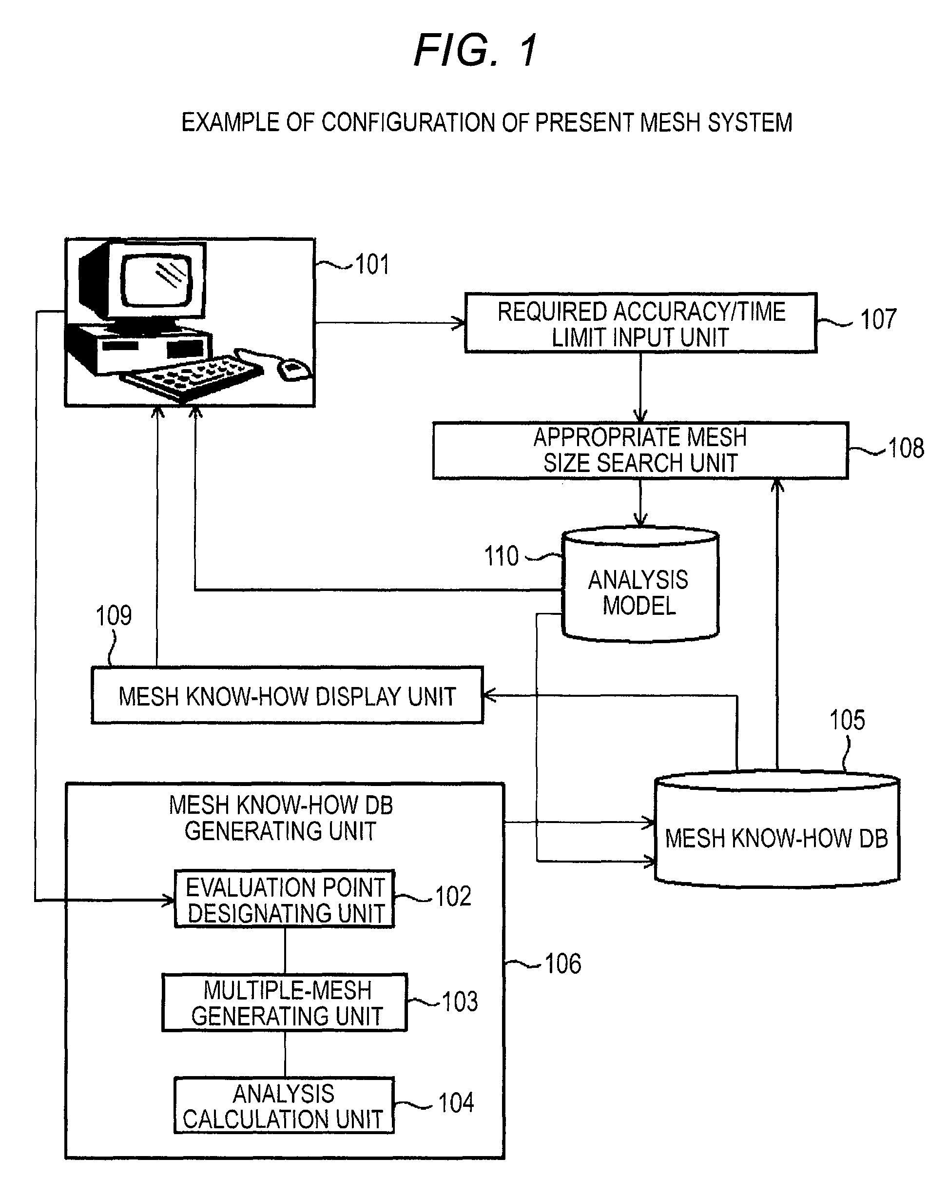
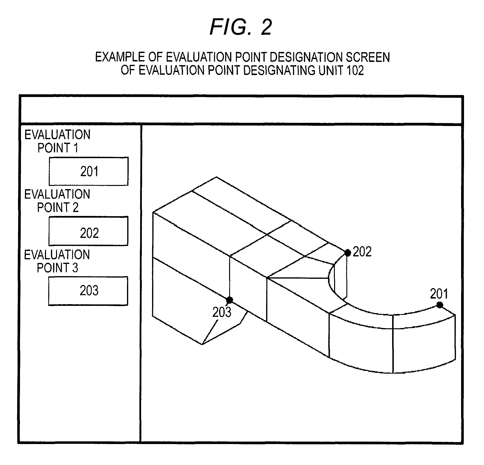
[0032]FIG. 1 shows the configuration of an embodiment of a mesh generation system according to the invention. The mesh generation system shown in FIG. 1 includes: an input / output device 101 having a keyboard, pointing device, display or the like for a system user to input data or to have data displayed; and a mesh know-how DB generating unit 106 having an evaluation point designating unit 102 which has a measure to designate an evaluation point (site) on an analysis target shape, a multiple-mesh generating unit 103 which creates meshes of plural types of mesh size, and an analysis calculation unit 104 which carries out analysis calculation with respect to plural mesh models created by the multiple-mesh generating unit 103, the mesh know-how DB generating unit 106 registering, in a mesh know-how DB 105, a relation among mesh size, analysis result and calculation time (“time” is considered as “cost” and therefore can be considered as “...

embodiment 2

Other Examples of Configuration

(1) Prediction of Calculation Time and Analysis Accuracy

[0061]The user predicts calculation time and analysis accuracy from the mesh size and the mesh know-how DB.

[0062]For example, the system user inputs a mesh size (in FIG. 8, this includes an overall mesh size, designation of a controlled density part 1 indicating a place where the mesh size should locally be made denser, and a denser mesh size to be achieved) into a mesh size input form 801, using a screen as shown in FIG. 8. If a calculation time / analysis accuracy estimate button 802 is pressed, the value of the analysis result and the calculation time are approximated by a function having the mesh size as a variable, following procedures similar to the processing by the appropriate mesh size search unit 108. Using the mesh size inputted in the mesh size input form 801 as a variable of this function, the calculation time and the analysis accuracy are calculated and estimate values of the calculati...

embodiment 3

One Specific Example

[0068]An example in which an appropriate mesh size is calculated using an analysis target shape and analysis conditions indicated by a reference numeral 1101 in FIG. 11 will be described.

[0069]First, the evaluation point designating unit 102 designates an evaluation point. In this example, it is assumed that the position indicated by a reference numeral 1102 is designated as an evaluation point.

[0070]Next, the multiple-mesh generating unit 103 and the analysis calculation unit 104 carry out processing to repeat analysis calculation while reducing the mesh size. The mesh know-how DB generating unit 106 registers the result of the processing in the mesh know-how DB 105. In this example, it is assumed that values in the table indicated by a reference numeral 1103 are registered in the mesh know-how DB 105. The amount of displacement is used as the value of the analysis result. When the mesh know-how display unit 109 displays this mesh know-how DB, a graph as shown i...


PUM


Abstract

Generation of a mesh model that can be analyzed with sufficient analysis accuracy for result evaluation and within a minimum possible calculation time even if a user does not grasp a tradeoff relation between analysis accuracy and analysis time due to mesh size is made possible. A mesh generation system designates an evaluation point (site) on an analysis target shape, analyzes plural analysis model data created with plural types of mesh size, stores a relation among mesh size, analysis result and calculation time in a mesh know-how DB, search for a mesh size which meets a required accuracy and calculation time limit, sets the mesh size that is found by the search to an analysis model. And displays the relation among mesh size, analysis result and calculation time.

Description

FIELD OF THE INVENTION[0001]The present invention relates to a CAE (computer aided engineering) system which numerically simulates a physical phenomenon based on numeric analysis using a computer, and particularly to generation of a mesh in CAE.BACKGROUND ART[0002]In product development processes, CAE is utilized to reduce development costs and shorten design and development periods. In CAE, an analysis model is created from a shape model or the like generated on a CAD (computer aided design) system, and strength analysis, thermal analysis, vibration analysis or the like is carried out using an analysis method, for example, the finite element method or the boundary element method, with that analysis model. In the generation of an analysis model in CAE as described above, first, the work of creating a mesh model from a shape model and setting boundary conditions or the like on each element of the mesh model is required, and a lot of time and effort is needed particularly to create a ...

Claims


Application Information

Patent Timeline
Patent Type & Authority Patents(United States)
IPC IPC(8): G06F17/50G06T17/20
CPCG06F17/50G06T17/20G06F30/00
Inventor ONODERA, MAKOTONISHIGAKI, ICHIRO
Owner HITACHI LTD
Why Eureka
Try Eureka