
Rapid disconnect device

a technology of fast disconnection and device, which is applied in the direction of resistors, non-adjustable resistors, heating/cooling contact switches, etc., can solve the problems of plurality of different faults, further damage, and inability to optimize the essential functions of the point of separation, so as to achieve the effect of fast disconnection and simple means

Active Publication Date: 2015-09-08
DEHN SOHNE GMBH CO KG
View PDF23 Cites 4 Cited by
  • Summary
  • Abstract
  • Description
  • Claims
  • Application Information

AI Technical Summary

Benefits of technology

The invention provides a fast disconnection device for surge arresters that can disconnect quickly before a critical temperature is reached and prevent damage or overload. The device is designed to have a short release time, making it reliable in multiple fault events. The lost element and its fixing means have low thermal capacity and conductivity, ensuring efficient heat utilization and fast response times.

Problems solved by technology

An optimization of the essential functions of the point of separation, namely the desired disconnection from the varistor when it is heated, is thus not possible.
Therefore, the solutions according to the prior art are forced to find compromises.
However, an overloaded varistor can lead to undefined influences with respect to the resulting fault currents and, thus, to a plurality of different faults and further damages.
The effort required for the detection of the fault current and the actuation of the switch as well as for the necessary evaluation is considerable, however.
Such an assembly, too, is constructively complicated and has the drawback that the release characteristic of the switch can be adapted to the requirements of the varistor to a limited extent only.
The prolongation of the isolating distance is therefore not only limited, but is also very slow, so that the switching capacity of the isolating distance as a whole remains reduced.
Also, the expansion of the expanding substance takes place with a delay so that a fast disconnection required in the event of a fault cannot be realized.
It becomes obvious that all solutions known from the prior art are only compromises between the possible, obtainable thermal sensitivity of the point of separation and the required current carrying capacity.
As a rule, the thermal disconnection devices have a considerable inertia which is due to the good thermal conductivity of the used materials and the necessary large cross-sections for contacts along with a great thermal capacity resulting therefrom.

Method used


Image

  • Rapid disconnect device
  • Rapid disconnect device
  • Rapid disconnect device

Examples


Embodiment Construction

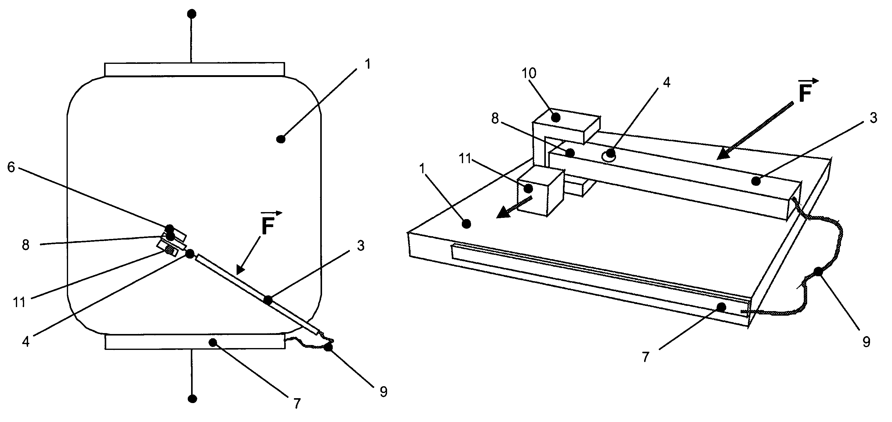
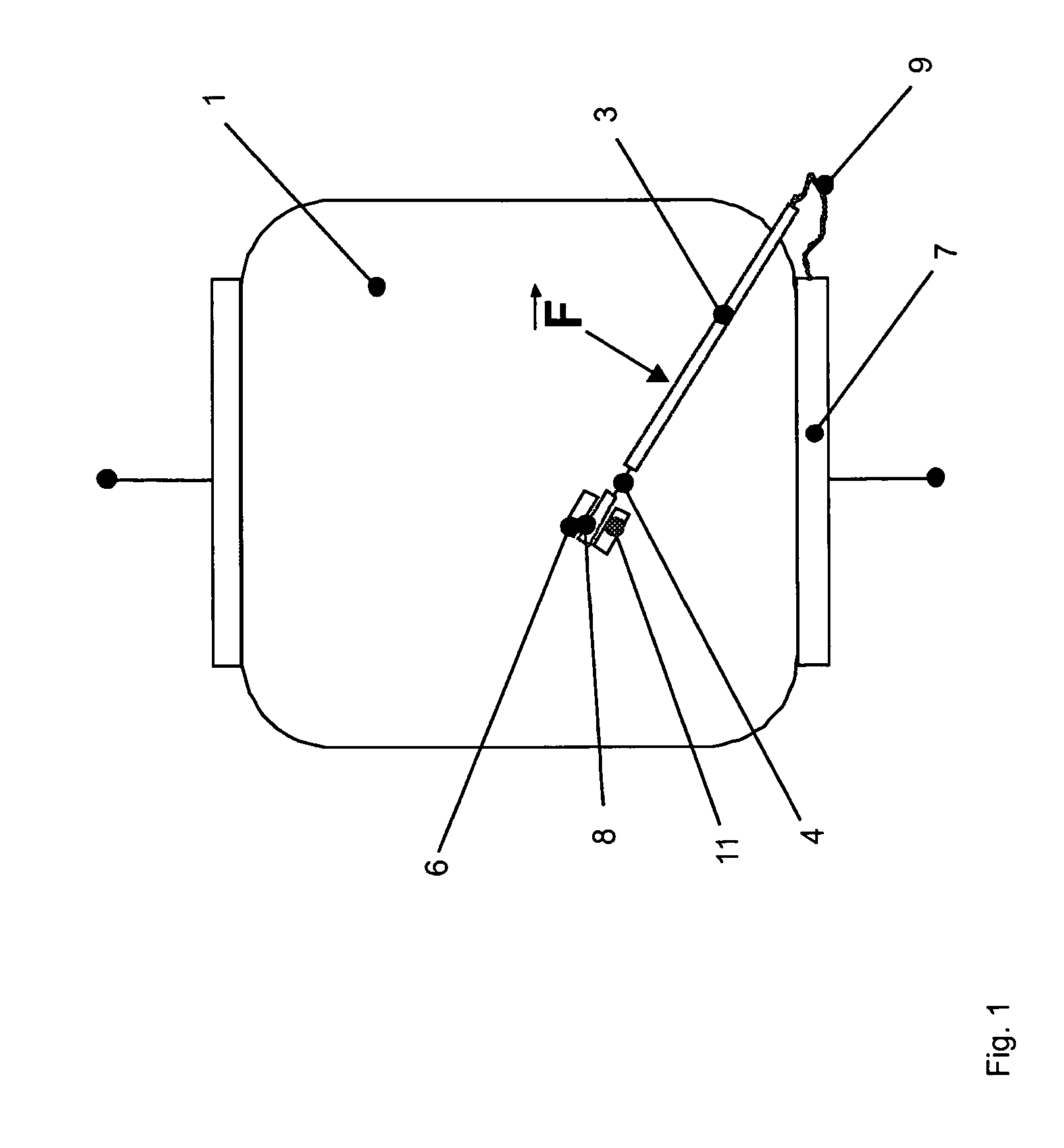
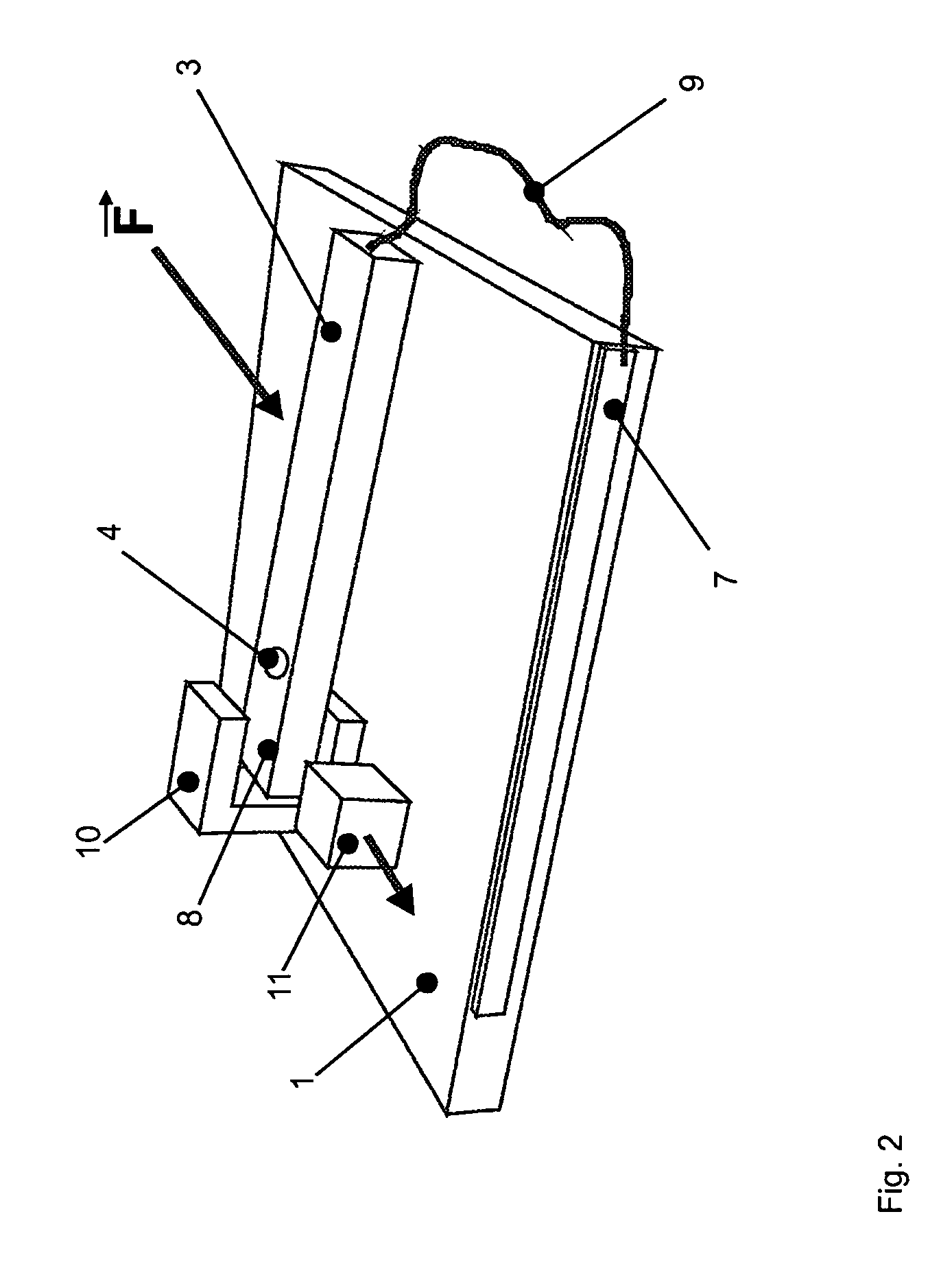
[0036]It is known that portions of varistors are heated differently, which is due to the installation situation, the material composition, the geometry and their contacting of the contact plates as well as the current distribution.

[0037]This means, in accordance with the aforementioned conditions, the point and / or region heated strongest is to be chosen for positioning the thermally separable means.

[0038]The thermally separable means and the part fixed by it, respectively, if in direct contact with the varistor, should be realized such that the thermal capacity is as low as possible and also the heat dissipation is reduced.

[0039]By avoiding that the chosen positioning point is influenced by the heating caused by an undesired heat dissipation it is ensured the intended, fastest possible temperature-sensitive disconnection of the varistor and, thus, an optimum adaptation for the protection thereof. Preferably, the response temperature of the thermally separable means is slightly above...


PUM


Abstract

The invention relates to a rapid disconnect device for surge arrestors, in particular plate-type or flat varistors, comprising at least one element that is maintained under a mechanical stress, and a disconnection point for disconnecting the surge arrestor from the respective power grid upon thermal overload, wherein the disconnection point comprises contacts, the positions of which vary relative to one another, wherein one of said contacts is designed to be fixed. According to the invention, the contacts of varying positions relative to one another are electrically connected without the use of solder in such a way that incident current forces act primarily in the contact force direction and such that the moving contacts of the positionally-variable contacts of a lost element located at the surge arrestor and thermally detachable therefrom can be moved from a closed position to the disconnected position.

Description

STATEMENT REGARDING FEDERALLY SPONSORED RESEARCH OR DEVELOPMENT[0001]Not ApplicableTHE NAMES OF THE PARTIES TO A JOINT RESEARCH AGREEMENT[0002]Not ApplicableINCORPORATION-BY-REFERENCE OF MATERIAL SUBMITTED ON A COMPACT DISC[0003]Not ApplicableBACKGROUND OF THE INVENTION[0004](1) Field of the Invention[0005]The invention relates to a fast disconnection device for surge arresters, specifically disc-shaped or flat varistors, comprising at least one element held under a mechanical preload as well as a point of separation in order to disconnect the surge arrester from the respective mains in the event of a thermal overload, wherein the point of separation includes contacts, the positions of which are variable relative to each other, and wherein one of these contacts is a fixed one.[0006](2) Description of Related Art[0007]Disconnection devices of common efficient surge arresters with In>15 kA 8 / 20 μs including varistors for use in low-voltage mains generally comprise a soldered connec...

Claims


Application Information

Patent Timeline
IPC IPC(8): H01H37/76H01T1/14H01C7/12H01H77/04
CPCH01T1/14H01C7/126H01H37/76H01H37/761H01H37/764
Inventor EHRHARDT, ARNDSCHREITER, STEFANIE
Owner DEHN SOHNE GMBH CO KG
Learn More