Molded load bearing surface and method of manufacture

a technology of load bearing surface and manufacturing method, which is applied in the direction of chair, furniture parts, machine supports, etc., can solve the problems of inability to tune the characteristics of a conventional molded seat, inconvenient and sometimes ergonomically unacceptable load bearing surface, and inability to provide the level of support and comfort available in more expensive load bearing surface, etc., to achieve convenient manufacture and mounting, simple and effective structure and method, and easy to mount

Active Publication Date: 2015-09-15
ILLINOIS TOOL WORKS INC
View PDF11 Cites 5 Cited by
  • Summary
  • Abstract
  • Description
  • Claims
  • Application Information

AI Technical Summary

Benefits of technology

[0010]The present invention provide a simple and effective structure and method that facilitates both manufacture and mounting of oriented, molded load bearing surfaces. The orienting members provide a rigid structure that can be readily mounted to a support structure using snaps, fasteners or other mounting elements. The orienting members also provide the load bearing surface assembly with rigid edge members that can be easily engaged by an orienting apparatus, thereby facilitating orientation of the load bearing surface through elongation. The mechanical interlock between the orienting members and the load bearing surface can be controlled in part through the design and configuration of the interlocking features of the orienting member.

Problems solved by technology

Although these molded chairs provide an inexpensive seating option, they do not provide the level of support and comfort available in more expensive load bearing surfaces, such as conventional cushion sets.
In seating and other body-support applications, this may result in an uncomfortable and sometimes ergonomically unacceptable load bearing surface.
Further, the ability to tune the characteristics of a conventional molded seat is relatively limited.
Different materials and different material thicknesses can be used to provide a limited degree of control over the characteristics of the seat, but this level of control is not sufficient in many applications.

Method used


Image

  • Molded load bearing surface and method of manufacture
  • Molded load bearing surface and method of manufacture
  • Molded load bearing surface and method of manufacture

Examples


Embodiment Construction

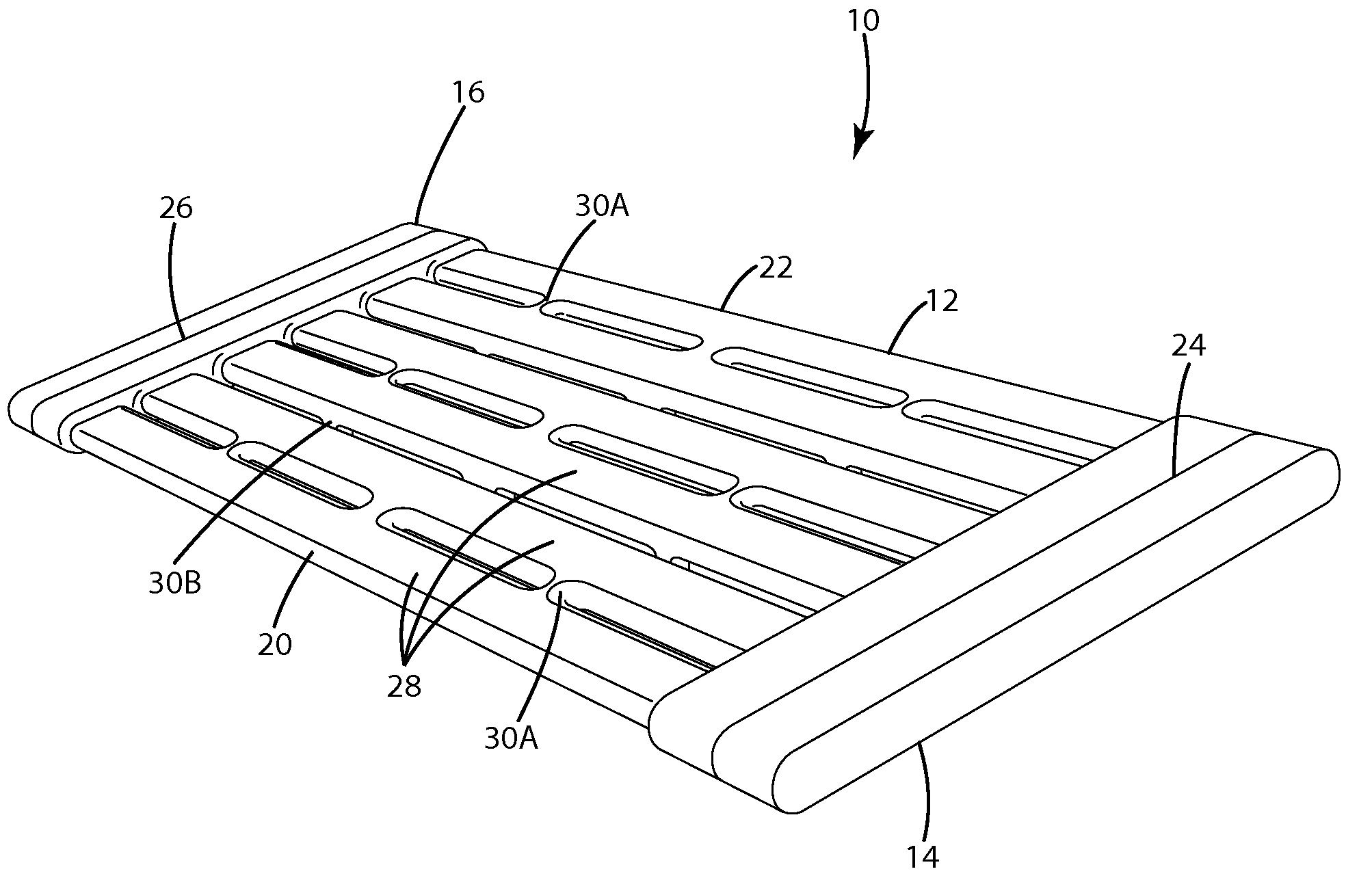
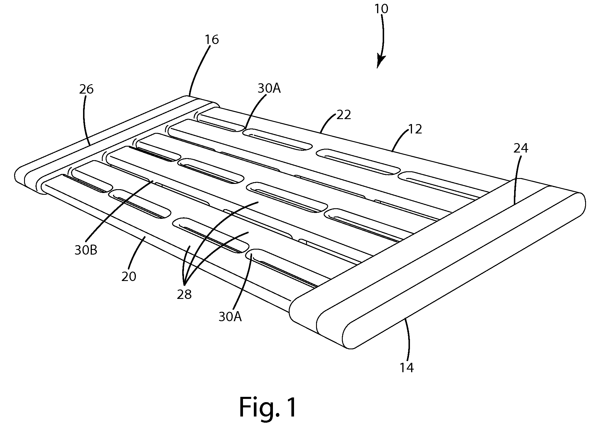
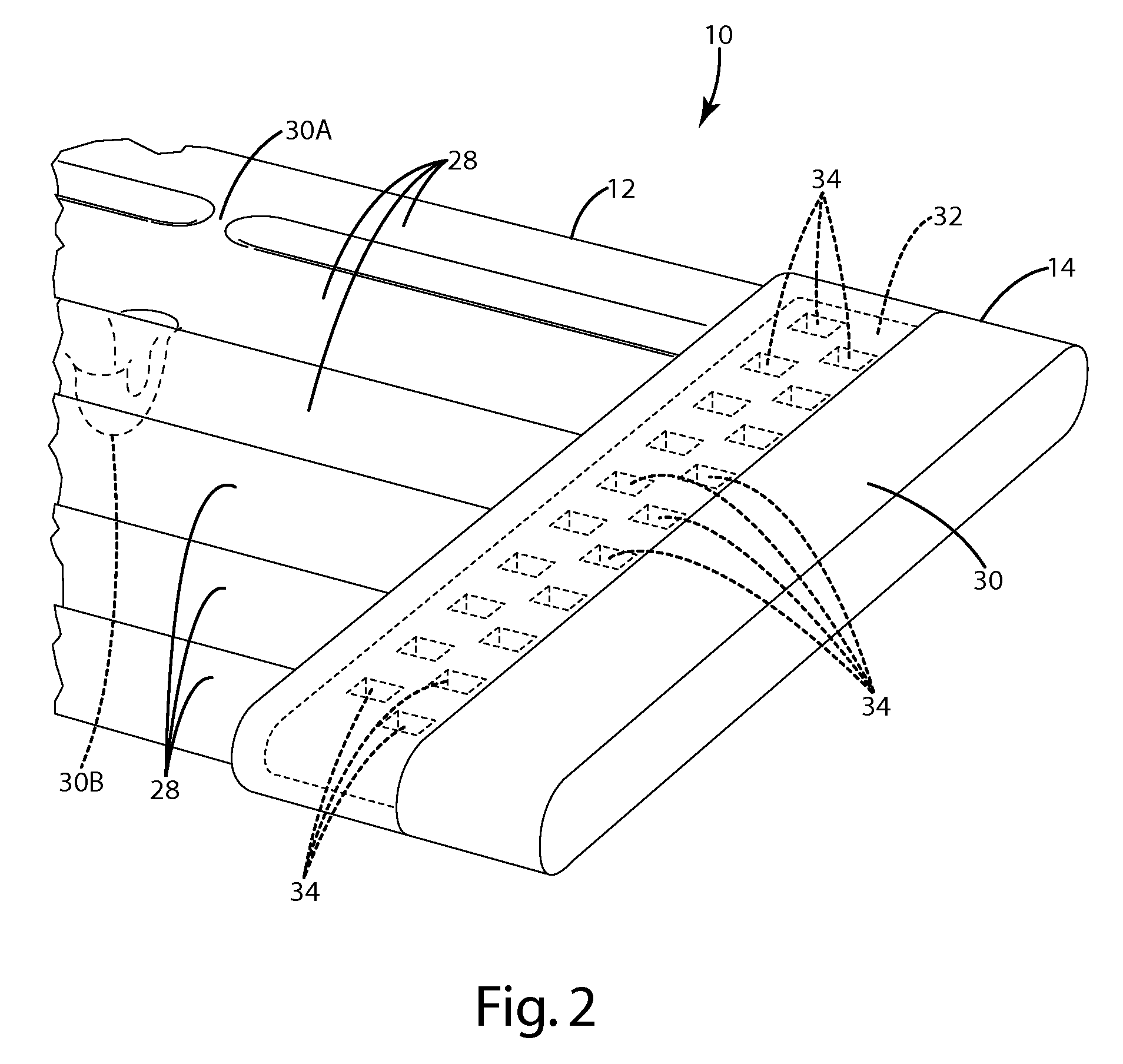
[0036]A load bearing surface assembly 10 in accordance with one embodiment of the present invention is shown in FIG. 1. The load bearing surface assembly 10 generally includes a load bearing surface 12 and a pair of orienting members 14, 16 disposed on opposed edges of the load bearing surface 12. The orienting members 14, 16 provide a rigid edge member that may be used to orient the load bearing surface 12 and / or to mount the load bearing surface 12 to a support structure.

[0037]In a second aspect, the present invention discloses a method for manufacturing a load bearing surface assembly including the general steps of: (1) providing a pair of orienting members 14, 16; (2) placing the orienting members 14, 16 in a mold cavity at opposed ends of the mold cavity; (3) molding a load bearing surface 12 onto the orienting members to form a load bearing surface assembly 10; and (4) orienting the load bearing surface 12 with an orienting apparatus (not shown), the orienting apparatus mating...


PUM

PropertyMeasurementUnit
shear strengthaaaaaaaaaa
elastomeric propertiesaaaaaaaaaa
hardnessaaaaaaaaaa

Abstract

A load bearing surface assembly has an oriented, molded load bearing surface intersecured with a relatively rigid orienting member. The characteristics of the orienting member are selected such that the orienting member provides a rigid edge member for holding the load bearing surface during the orienting process and / or for mounting the load bearing surface to a support structure. A pair of orienting members are mounted to opposed edges of the load bearing surface. The load bearing surface may be integrally molded into a unitary construction with the orienting member(s). Methods for manufacturing a load bearing surface having an orienting member and a load bearing surface assembly with a load bearing surface and an orienting member are also disclosed.

Description

CROSS REFERENCE TO RELATED APPLICATION[0001]This application is national phase of PCT / US2010 / 023576 filed Feb. 9, 2010, and claims the benefit of U.S. Provisional Application No. 61 / 158,982, filed Mar. 10, 2009.FIELD OF THE INVENTION[0002]The present invention relates to load bearing surfaces, and more particularly to molded load bearing surfaces, such as the seat or back of a chair or bench, or the support surface of a bed, cot or other similar product.BACKGROUND OF THE INVENTION[0003]There are continuing efforts to develop new and improved load bearing surfaces. In the context of general load bearing surfaces, the primary objectives of these efforts are to obtain a durable and inexpensive load bearing surface. In the context of seating and other body-support applications, it is also important to address comfort issues. For example, with seating, it can be important to provide a surface that is comfortable and does not create body fatigue over periods of extended use. Given that th...

Claims


Application Information

Patent Timeline
Patent Type & Authority Patents(United States)
IPC IPC(8): A47C23/00B29C45/14A47C7/14B29C45/00A47C7/28B29L31/44
CPCA47C7/287A47C7/14A47C7/282B29C45/0062B29C45/14311B29C45/14336B29L2031/443
Inventor COFFIELD, TIMOTHY P.
Owner ILLINOIS TOOL WORKS INC
Why Eureka
Try Eureka