Electrosurgical tool cover

a tool cover and electrosurgical technology, applied in the field of surgical instruments or tools, can solve the problems of preventing the electricity generated by the instrument, affecting the solution of another, and affecting the solution, so as to achieve the effect of high tear strength, high tensile strength, and high tear strength

Active Publication Date: 2015-09-22
INTUITIVE SURGICAL OPERATIONS INC
View PDF52 Cites 46 Cited by
  • Summary
  • Abstract
  • Description
  • Claims
  • Application Information

AI Technical Summary

Benefits of technology

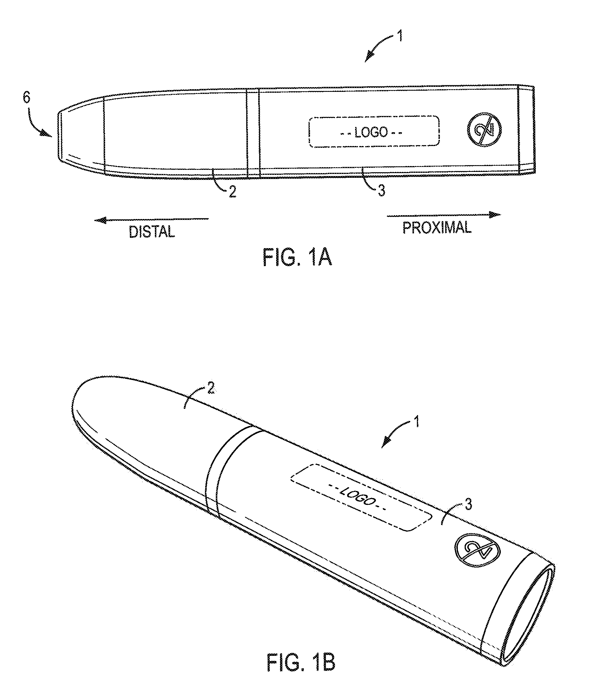
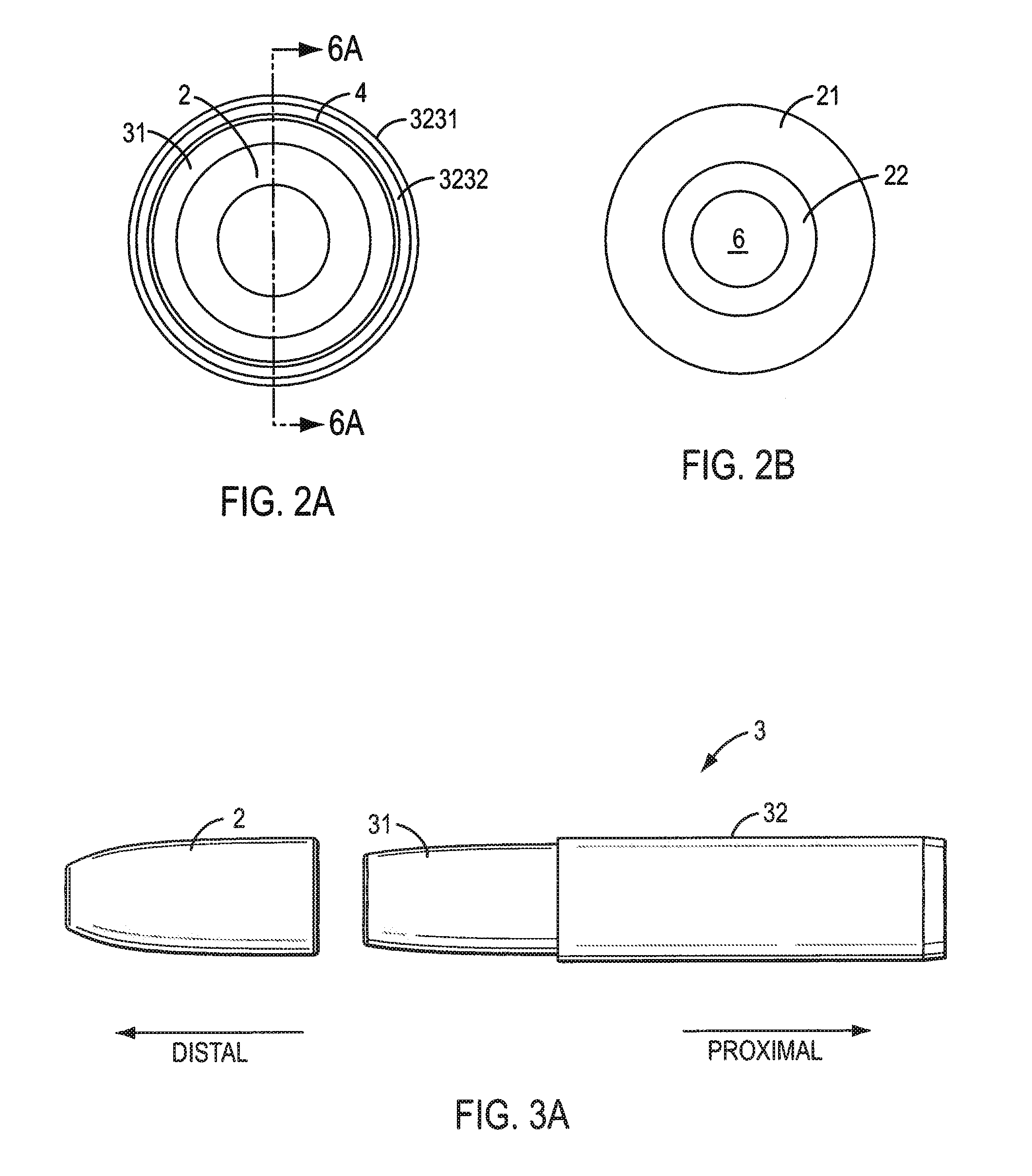
[0013]In accordance with various exemplary embodiments of the present teachings, the present teachings contemplate a cover for an electrosurgical instrument having a wrist structure and an end effector. The cover includes a hollow elongated structure. The hollow elongated structure includes a tip cover portion and a base cover portion. The tip cover portion has a distal end with an opening therethrough sized to receive the end effector of the electrosurgical instrument and is composed of a first, electrically insulative material having a flexibility sufficient to allow the end effector to be manipulated while the end effector is received in the opening. The base cover portion is integrally connected to the tip cover portion and is composed of a second material having a higher tear strength than the first material. The tip cover portion and the base cover portion overlap at an overlap region configured to receive the wrist structure of the electrosurgical instrument when the end effector is received in the opening.
[0014]In accordance with at least one exemplary embodiment, the present teachings contemplate a cover for an electrosurgical instrument having a wrist structure and an end effector. The cover includes a hollow elongated composite material structure having an end with an opening therethrough sized to receive the end effector of the electrosurgical instrument. The hollow structure includes a first distal region, a second proximal region and a transition region in which the first material surrounds the second material. The first distal region includes the end with the opening and is composed of a first electrically insulative material having a flexibility sufficient to allow the end effector of the electrosurgical instrument to be manipulated while the end effector is received in the opening. The second proximal region is composed of a second material having a higher tear strength than the first material. The transition region is disposed between the first distal region and the second proximal region.
[0015]In accordance with at least one exemplary embodiment, the present teachings contemplate a cover for an electrosurgical instrument having a wrist structure and an end effector. The cover includes a hollow elongated composite material structure having an end with an opening therethrough sized to receive the end effector of the electrosurgical instrument. The hollow structure includes a first distal region, a second proximal region and a transition region in which the first material surrounds the second material. The first distal region includes the end with the opening and is composed of a first electrically insulative material having a flexibility sufficient to allow the end effector of the electrosurgical instrument to be manipulated while the end effector is received in the opening. The second proximal region is composed of a second material having a higher tensile strength than the first material. The transition region is disposed between the first distal region and the second proximal region.

Problems solved by technology

However, electrosurgical treatments performed via minimally invasive (e.g., endoscopic) surgery can be riskier than traditional open procedures.
Such an approach, however, can pose difficulties in attempting to prevent the electricity generated by the instrument from traveling outside the desired path and burning tissue at an undesired location, e.g., away from the end effector.
Some examples of the challenging design considerations that are presented in minimally invasive and / or robotically controlled electrosurgery applications include the narrow passages (e.g., cannulas, body orifices, body tissue geometry) in which instruments are advanced and operated, the relatively wide and varied range of angular movement of the wrist that is desired, the wet environment (e.g., blood, saline, etc.) in which the instruments must operate, the high electrical energy and temperature ranges in which the instruments operate, the repeated (e.g., cyclical) movement to which the wrist and end effector are subjected, and / or the abrasive and / or relatively high impact forces that can be exerted on the instrument during operation, for example, as a result of collision with other instruments, bone, and / or sharp edges of various objects (such as the end of the cannula when the instrument is withdrawn).
Complicating things even further is the fact that many of these design considerations compete with one another such that finding an optimal solution to address one issue may negatively impact a solution to another.

Method used


Image

  • Electrosurgical tool cover
  • Electrosurgical tool cover
  • Electrosurgical tool cover

Examples


Embodiment Construction

[0046]This description and the accompanying drawings illustrate exemplary embodiments and should not be taken as limiting, with the claims defining the scope of the present teachings. Various mechanical, compositional, structural, electrical, and operational changes may be made without departing from the scope of this description and the invention as claimed, including equivalents. In some instances, well-known structures, and techniques have not been shown or described in detail so as not to obscure the disclosure. Like numbers in two or more figures represent the same or similar elements. Furthermore, elements and their associated aspects that are described in detail with reference to one embodiment may, whenever practical, be included in other embodiments in which they are not specifically shown or described. For example, if an element is described in detail with reference to one embodiment and is not described with reference to a second embodiment, the element may nevertheless b...


PUM


Abstract

A cover for an electrosurgical instrument having a wrist structure and an end effector is provided. The cover includes a hollow elongated structure, which includes a tip cover portion and a base cover portion integrally connected to the tip cover portion. The tip cover portion has a distal end with an opening therethrough sized to receive the end effector of the electrosurgical instrument and is composed of a first, electrically insulative material having a flexibility sufficient to allow the end effector to be manipulated while the end effector is received in the opening. The base cover portion is composed of a second material having a higher tear strength than the first material. The tip cover portion and the base cover portion overlap at an overlap region configured to receive the wrist structure of the electrosurgical instrument when the end effector is received in the opening.

Description

CROSS-REFERENCE TO RELATED APPLICATIONS[0001]This application claims the benefit of U.S. Provisional Application No. 61 / 362,916, filed Jul. 9, 2010, which is hereby incorporated by reference herein in its entirety.TECHNICAL FIELD[0002]The present teachings are generally directed to electrosurgical instruments or tools. More particularly, aspects of the present teachings relate to wristed electrosurgical instrument tool covers that can inhibit or prevent conduction of electrical current from an electrically live wristed tool to the patient or other undesirable locations near the surgical site.INTRODUCTION[0003]Various electrosurgical treatment instruments, which generally use high-frequency alternating current, treat tissue of an organism, e.g., a human patient, using heat produced by electrical energy while cutting, shearing, grasping, or contacting the tissue. Such instruments are used to perform a variety of treatments, such as, for example, incision, coagulation, ablation, and th...

Claims


Application Information

Patent Timeline
Patent Type & Authority Patents(United States)
IPC IPC(8): A61B17/00A61B18/14A61B19/00A61B18/00
CPCA61B18/1445A61B19/40A61B19/2203A61B2018/00083A61B34/30A61B90/04A61B2090/0436
Inventor KROM, JUSTINGONG, KENNETH L.GRESHAM, RICHARD D.MANZO, SCOTT E.ORBAN, III, JOSEPH P.
Owner INTUITIVE SURGICAL OPERATIONS INC
Why Eureka
Try Eureka