Multi power source power supply

a power supply and multi-power technology, applied in the field of battery housing, can solve the problems of heavy battery type, difficult to replace, and difficult to meet the needs of users,

Active Publication Date: 2015-09-22
MAQUET CARDIOVASCULAR LLC
View PDF16 Cites 1 Cited by
  • Summary
  • Abstract
  • Description
  • Claims
  • Application Information

AI Technical Summary

Benefits of technology

[0011]A medical device, such as an intra-aortic balloon pump, according to an example embodiment of the present invention includes a pump, a lock element, a power-source housing, and a control unit adapted to control the pump. An interior of the power-source housing including a first housing part and a second housing part. The first housing part is configured to hold a first power source. The second housing part is configured to hold a second power source. The first housing part includes a first opening large enough for the first power source to pass through. The second housing part includes a second opening large enough for the second power source to pass through. The power-source housing is accessible such that the first power source and the second power source can be replaced without dismantling the intra-aortic balloon pump. The power-source housing is configured such that when the first power source is being removed from the first housing part the lock element prevents simultaneous removal of the second power source from the second housing part and when the second power source is being removed from the second housing part the lock element prevents simultaneous removal of the first power source from the first housing part.
[0025]A container according to an example embodiment of the present invention includes a housing and a lock element. The housing defines a first housing part and a second housing part. The first housing part is configured to hold a first power source. The second housing part is configured to hold a second power source. The first housing part includes a first opening large enough for the first power source to pass through. The second housing part includes a second opening large enough for the second power source to pass through. The container is configured such that when the first power source is being removed from the first housing part, the lock element prevents simultaneous removal of the second power source from the second housing part and when the second power source is being removed from the second housing part, the lock element prevents simultaneous removal of the first power source from the first housing part.
[0030]A device according to an example embodiment of the present invention includes a power source, a lock element, and a power-source housing. An interior of the power-source housing includes a first housing part and a second housing part. The first housing part is configured to hold a first power source. The second housing part is configured to hold a second power source. The first housing part includes a first opening large enough for the first power source to pass through. The second part includes a second opening large enough for the second power source to pass through. The power-source housing is configured such that when the first power source is being removed from the first housing part the lock element prevents simultaneous removal of the second power source from the second housing part and when the second power source is being removed from the second housing part the lock element prevents simultaneous removal of the first power source from the first housing part.
[0035]A method, according to an example embodiment of the present invention, minimizes or completely avoids power supply disruption to a device. The device, e.g., a medical device such as an intra-aortic balloon pump or a ventilator, etc., includes a housing defining a first housing part and a second housing part and a lock element connected to the housing. The first housing part is configured to hold a first power source and the second housing part is configured to hold a second power source. The first housing part includes a first opening large enough for the first power source to pass through and the second housing part including a second opening large enough for the second power source to pass through. The method includes the steps of: (a) while the first power source is in the first housing part and the second power source is in the second housing part, moving the lock element from a first position at least partially blocking both the first opening and the second opening to a second position at least partially blocking the first opening and not blocking the second opening, such that the second power source can be removed from the second housing part and the first power source cannot be simultaneously removed from the first housing part; and (b) removing the second power source from the second housing part.

Problems solved by technology

Typically, the battery is integrated into an internal battery compartment and is not readily accessible for replacement while the IABP is in operation.
Therefore, if the battery is allowed to discharge, the IABP becomes unusable for patient transport and must be connected to an AC power source for recharging, some times for several hours.
This type of battery is heavy, bulky, and requires fasteners to connect to the terminals.
Due to the heavy weight of a lead-acid battery, heavy brackets are required to secure it within the IABP.
Further, lead-acid batteries have a finite number of charge / discharge cycles after which they are no longer capable of retaining a charge.
Replacement of a battery of this type is also labor intensive.

Method used


Image

  • Multi power source power supply
  • Multi power source power supply
  • Multi power source power supply

Examples


Embodiment Construction

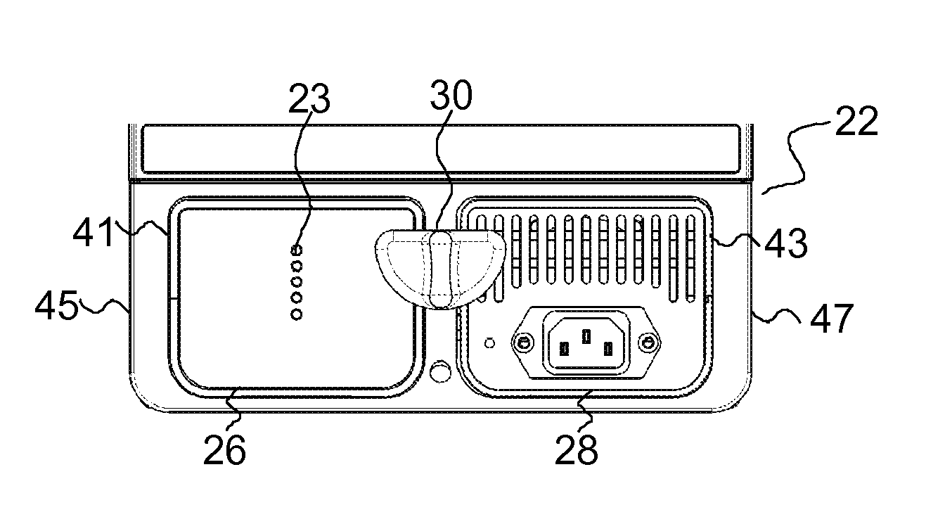
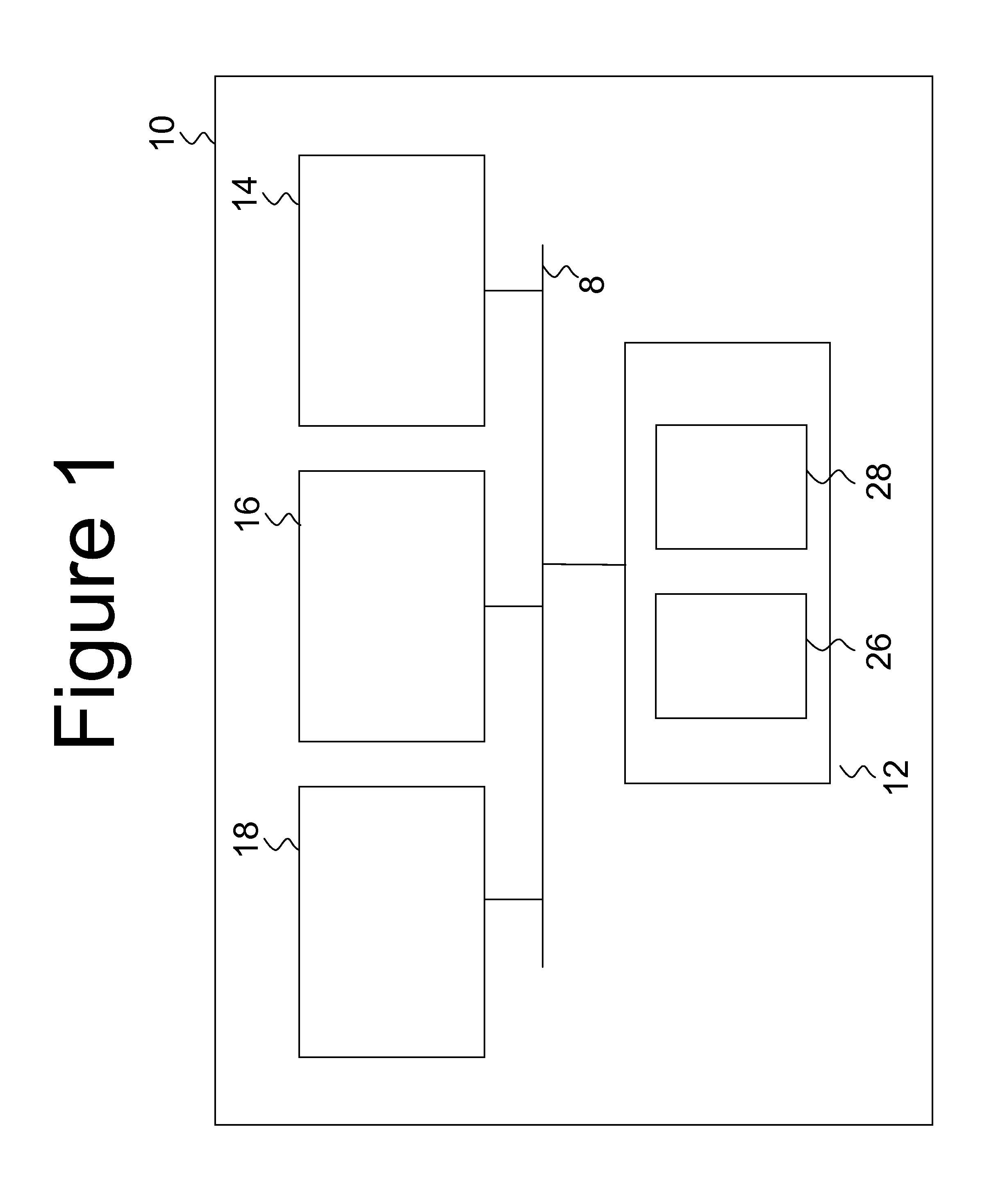
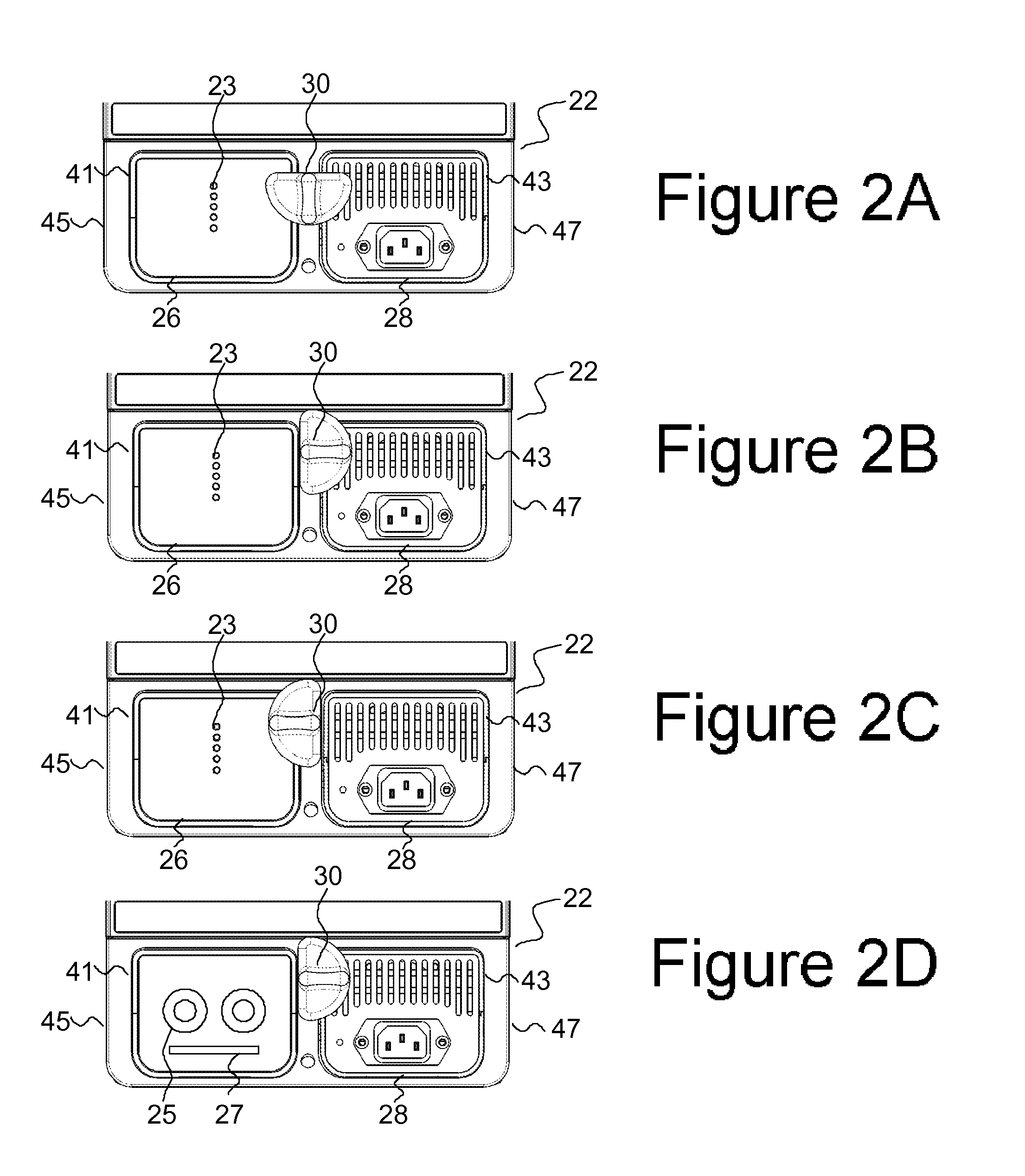
[0054]FIG. 1 illustrates a block diagram of an intra-aortic balloon pump (IABP) 10 according to an exemplary embodiment of the present invention. The IABP 10 is used to inflate and deflate a balloon on a distal end of a balloon catheter (not shown). The balloon catheter is typically inserted into a blood vessel of a patient and used to support the patient's heart. As detailed in U.S. Pat. No. 6,241,706, herein incorporated by reference in its entirety, the IABP 10 includes a power supply 12, a pump 14 (used interchangeably herein with compressor), a control unit 16, and bus 8. The power supply 12 will be discussed in more detail below. The control unit 16 includes a processor / CPU and a computer-readable storage medium for processing and storing data and / or instructions used by any of the other components of the IABP 10. The control unit 16 communicates with the various components of the IABP 10 through bus 8. The IABP 10 also includes a user input interface and display 18. The user ...


PUM

PropertyMeasurementUnit
lengthaaaaaaaaaa
lengthaaaaaaaaaa
poweraaaaaaaaaa

Abstract

A multiple power-source housing adapted to prevent simultaneous removal of more than a single power source, such as a battery, at a time. In an example embodiment, the power-source housing is used to house batteries for an intra-aortic balloon pump, which use battery power during transport. The power-source housing holds a first and second power source. When the first power source is removed, a mechanism, such as a knob, prevents simultaneous removal of the second power source or removal of the second power source until the first power source is replaced. Similarly, when the second power source is removed the mechanism prevents simultaneous removal of the first power source or removal of the first power source until the second power source is replaced.

Description

CROSS-REFERENCE TO RELATED APPLICATIONS[0001]Not applicable.STATEMENT REGARDING FEDERALLY SPONSORED RESEARCH OR DEVELOPMENT[0002]Not applicable.BACKGROUND OF THE INVENTION[0003]1. Field of the Invention[0004]The present invention generally relates to a battery housing. An exemplary embodiment of the present invention relates to a battery housing for a medical device such as an intra-aortic balloon pump.[0005]2. Description of Related Art[0006]Intra-aortic balloon pumps (IABPs) are used to provide pneumatic assistance to a failing or weakened heart. Often this therapy must be sustained as patients are transported within or between medical facilities.[0007]When an IABP is in a stationary mode, it is typically powered by the medical facility's AC power. The IABP incorporates an internal back-up battery used to provide power during transport or in case of AC power loss. Typically, the battery is integrated into an internal battery compartment and is not readily accessible for replacemen...

Claims


Application Information

Patent Timeline
Patent Type & Authority Patents(United States)
IPC IPC(8): A61N1/00A61M1/12A61M1/10H02J9/06H01M2/10H01M50/204H01M50/264
CPCA61M1/127A61M1/1072H02J9/061A61M2205/8206H01M2/1022F04C2270/041Y02E60/10A61M60/871A61M60/497A61M60/113A61M60/139A61M60/538A61M60/585A61M60/295H01M50/264H01M50/204H02J2310/23
Inventor KAUSHANSKY, YEFIM
Owner MAQUET CARDIOVASCULAR LLC
Why Eureka
Try Eureka