Wireless base station, wireless communication system, and wireless communication method
a wireless communication system and wireless communication technology, applied in multiplex communication, power management, high-level techniques, etc., can solve the problems of reducing the throughput of the entire wireless system, interfering between these signals, etc., and achieve the effect of preventing interference by pilot signals
- Summary
- Abstract
- Description
- Claims
- Application Information
AI Technical Summary
Benefits of technology
Problems solved by technology
Method used
Image
Examples
first embodiment
Configuration of Wireless Communication System
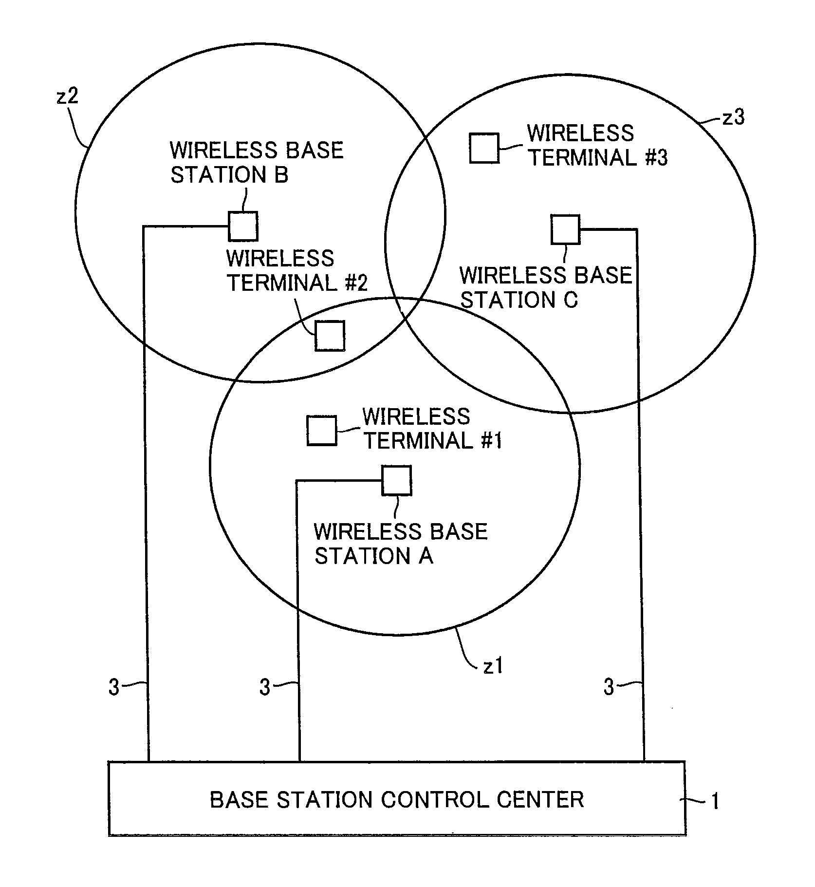
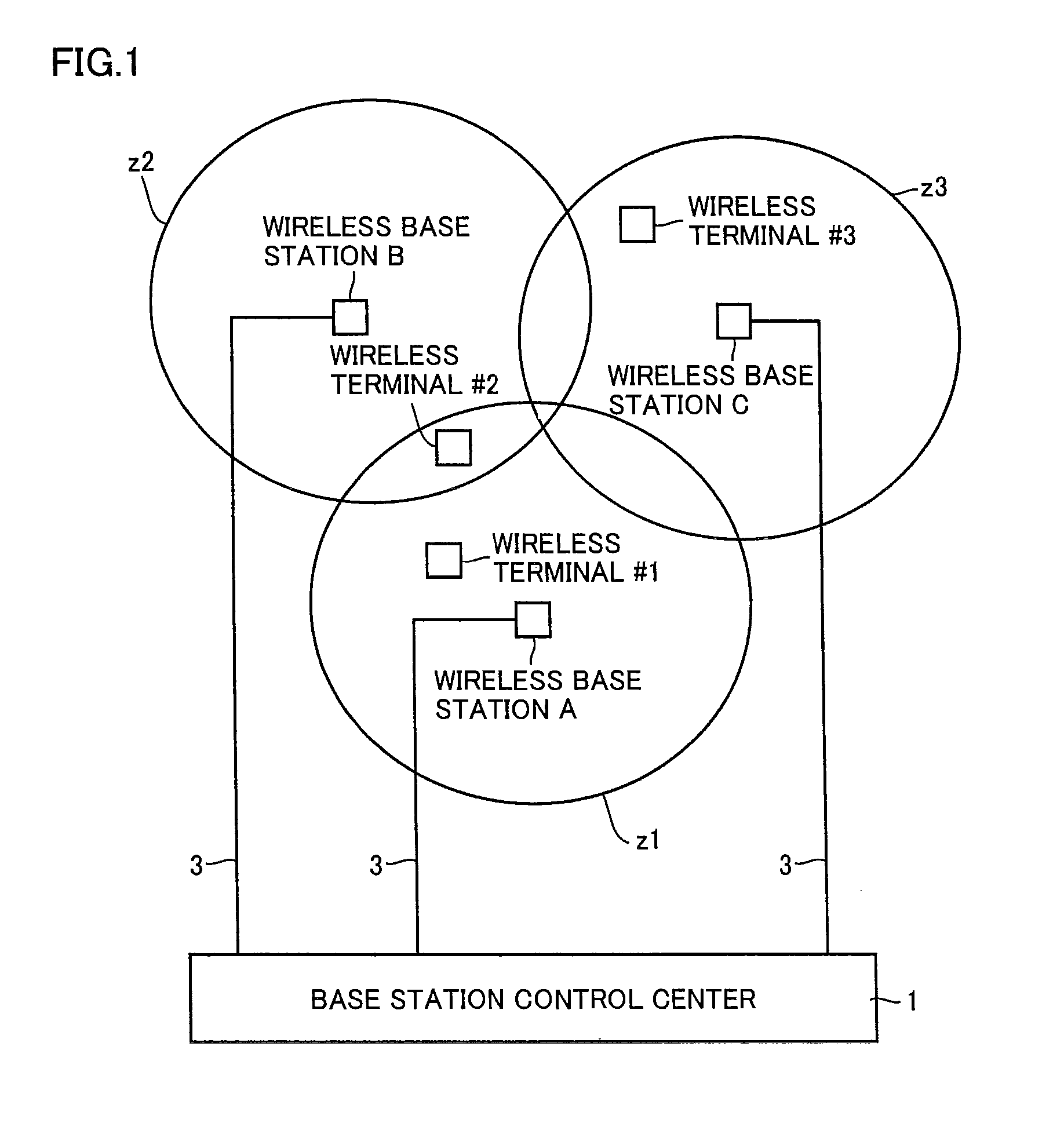
[0029]FIG. 1 shows a configuration of a wireless communication system of an embodiment of the present invention.
[0030]Referring to FIG. 1, wireless base stations A-C are arranged. Here, zones z1, z2, z3 respectively represent ranges in which electric waves are delivered from wireless base stations A, B, C. Zone z1 of wireless base station A overlaps with zones z2, z3 of the other wireless base stations B, C. Hence, for example, when a wireless terminal #2 is communicating with wireless base station A, a signal received by wireless terminal #2 from wireless base station A has interference with a signal from wireless base station B. Wireless base stations A-C are connected to base station control center 1 via network cables 3.
[0031](Configuration of Wireless Base Station)
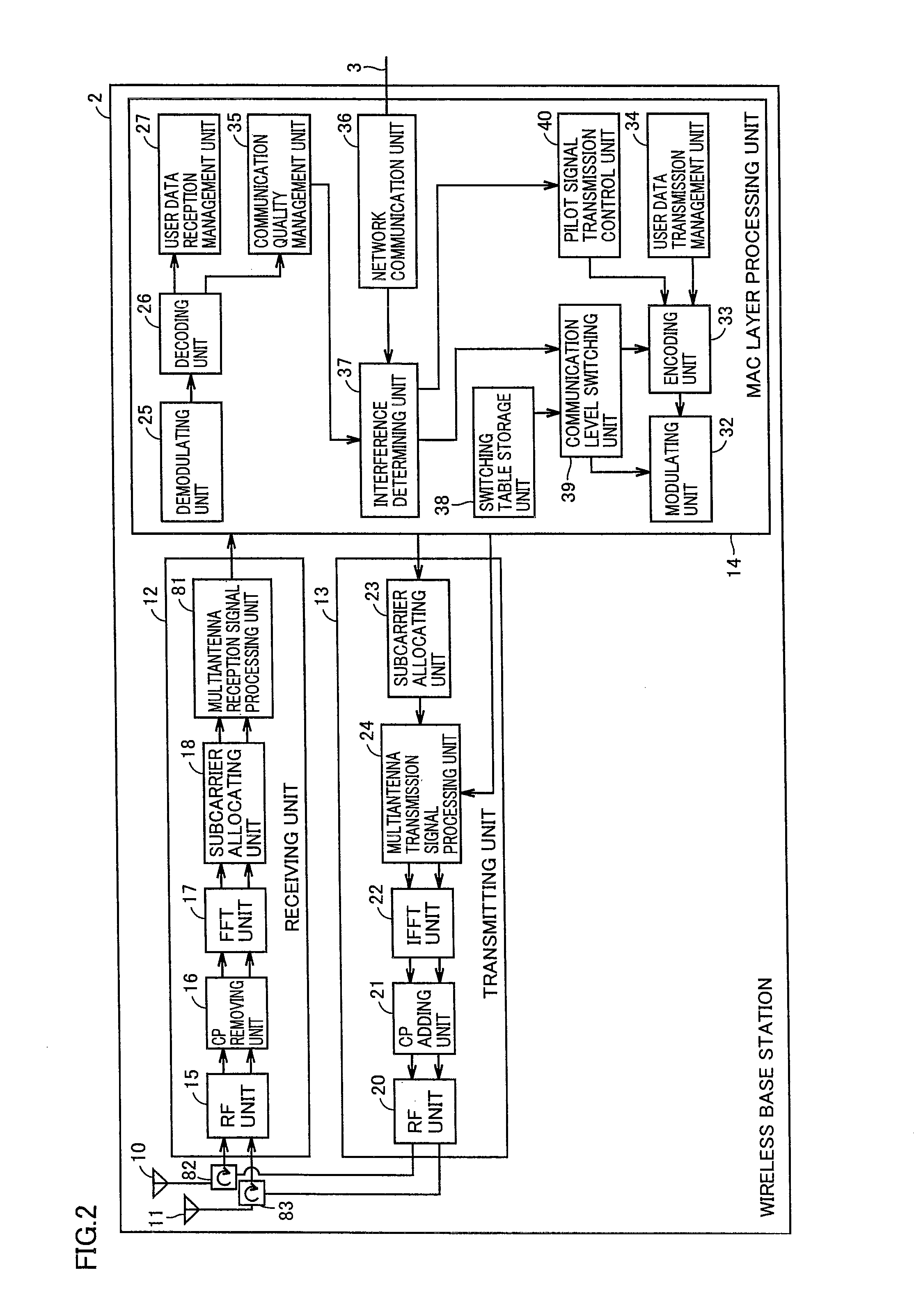
[0032]FIG. 2 shows a wireless base station of the embodiment of the present invention.
[0033]Referring to FIG. 2, this wireless base station 2 includes a first antenna 10, ...
second embodiment
[0097]An interference determining unit of a second embodiment is different from the interference determining unit of the first embodiment in terms of a method of determining whether or not there is interference.
[0098]FIG. 10 is a graph showing a relation between transmission power of the wireless terminal communicating with the wireless base station and a carrier to interference and noise ratio (DL_CINR) of a downlink signal transmitted from the wireless base station, the DL_CINR being measured by the wireless terminal communicating therewith.
[0099]In FIG. 10, L3 is a curve when there is no interference. L4 is an exemplary curve when there is interference.
[0100]Interference determining unit 37 stores the relation provided by the curve of L3 in advance, in the form of a table or a mathematical expression. Interference determining unit 37 calculates a normal value RR2 of the DL_CINR, which is obtained in the case where there is no interference and corresponds to a value P0 of the tran...
third embodiment
[0110]An interference determining unit of a third embodiment is different from the interference determining unit of each of the first and second embodiments in terms of a method of determining whether or not there is interference.
[0111](Operation)
[0112]FIG. 13 is a flowchart showing a procedure of an operation for control of transmission of the pilot signal and for control of switching of the communication level in the wireless base station of the third embodiment. The wireless base station performs the operation of the flowchart ofFIG. 13 whenever a predetermined time elapses.
[0113]The flowchart of FIG. 13 is different from the flowchart of FIG. 9 in a step S310.
[0114]Specifically, when the wireless base station is not communicating with a wireless terminal (YES in step S100), interference determining unit 37 calculates a threshold value by subtracting a predetermined value from the DL_RSSI of the wireless base station. The DL_RSSI is received from the wireless terminal. When an ad...
PUM
 Abstract
Description
Claims
Application Information
 - R&D
- Intellectual Property
- Life Sciences
- Materials
- Tech Scout
- Unparalleled Data Quality
- Higher Quality Content
- 60% Fewer Hallucinations
Browse by: Latest US Patents, China's latest patents, Technical Efficacy Thesaurus, Application Domain, Technology Topic, Popular Technical Reports.
© 2025 PatSnap. All rights reserved.Legal|Privacy policy|Modern Slavery Act Transparency Statement|Sitemap|About US| Contact US: help@patsnap.com


