Photo-voltaic maximum power point trackers

Active Publication Date: 2015-10-06
TECH UNIV EINDHOVEN
View PDF3 Cites 25 Cited by
  • Summary
  • Abstract
  • Description
  • Claims
  • Application Information

AI Technical Summary

Benefits of technology

[0018]According to one aspect of the invention, a multiplier is employed to generate a signal proportional to an output power of an array of the power generators when a peak in a load current or load voltage does not coincide with the maximum power point, or when an output current or output voltage cannot be used as a measure for output power. In one aspect a signal related to the output power of the power generator is used to feed the control loop.
[0019]According to another aspect of the invention, a Buck or

Problems solved by technology

It may even have multiple local maxima in its power curve, which makes finding the true optimum difficult.
This implies that it will be impossible to find a load that will cause each panel to work a

Method used


Image

  • Photo-voltaic maximum power point trackers
  • Photo-voltaic maximum power point trackers
  • Photo-voltaic maximum power point trackers

Examples


Embodiment Construction

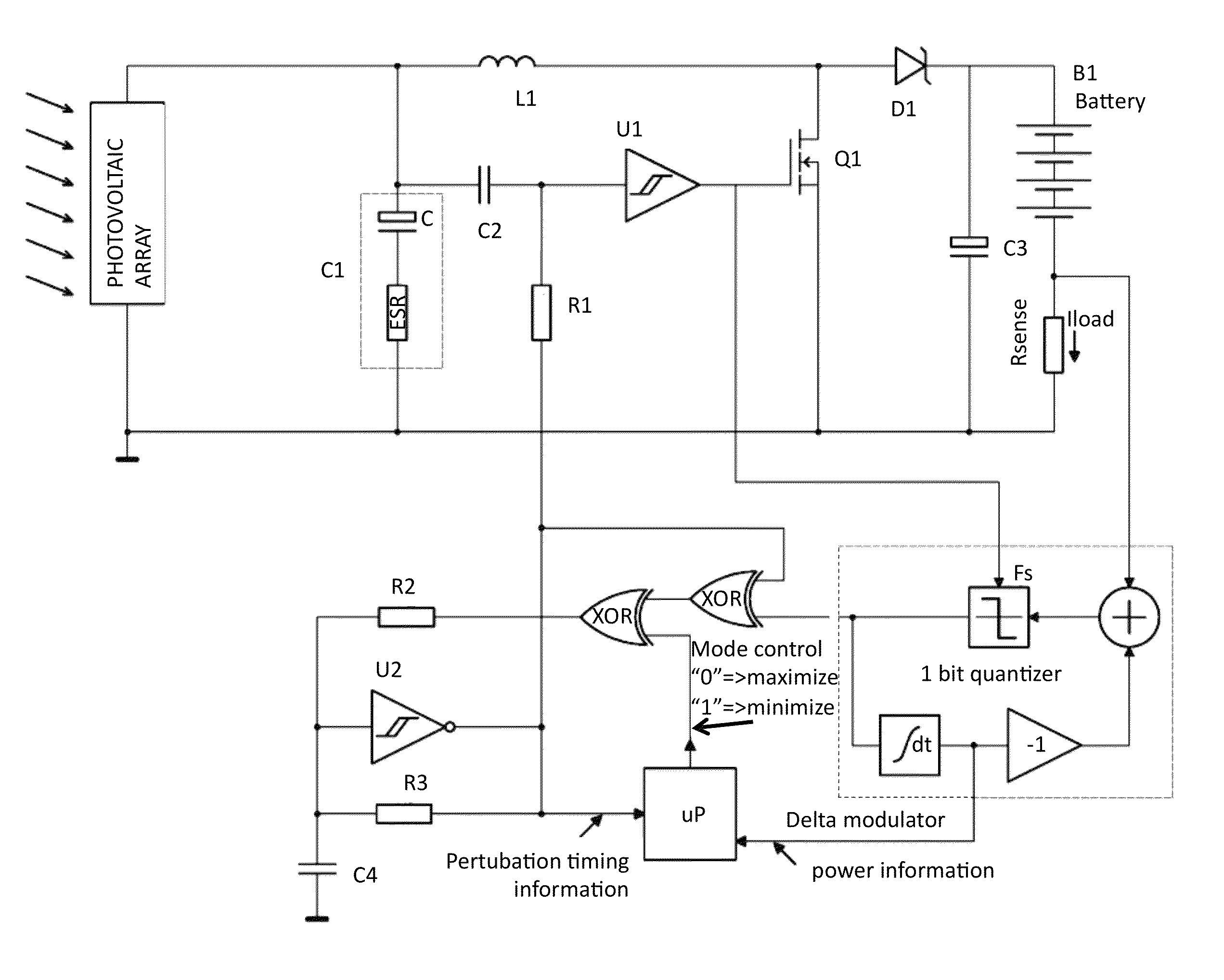
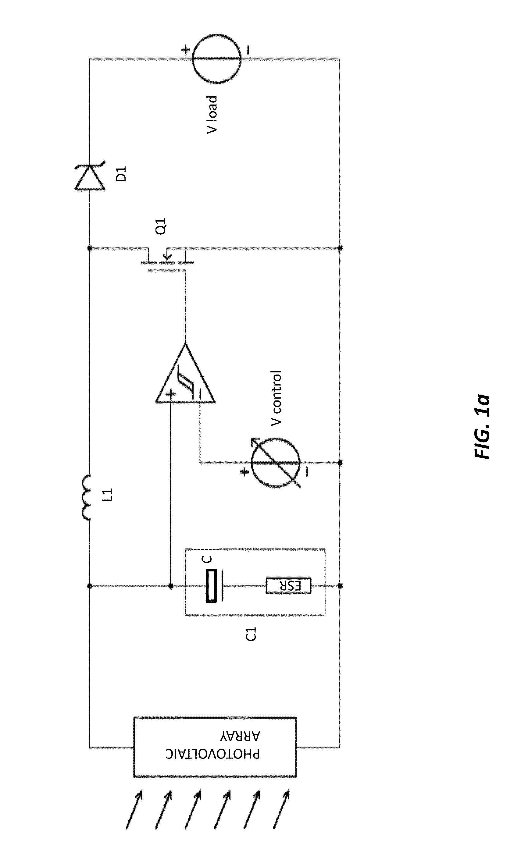
[0086]In order to extract the maximum possible amount of power from a photo-voltaic array (PV array) under varying insolation conditions and temperature, one embodiment of the current invention provides a circuit that steers the electrical operating point of the PV array towards an optimum. The maximum power point tracker (MPPT) imposes a load to the PV array such that its output power is maximized at the given conditions. A MPPT generally includes a power section and a control section. The power section or converter includes a form of switched mode topology that adapts the load to the PV array. The control section maximizes the output power by controlling the transfer ratio of the converter. This function can be implemented either in software or in analog or digital hardware.

[0087]In one embodiment of the invention, the power output of a non-ideal PV array is maximized, where maximum power point tracking is performed locally instead of centralized. In a further embodiment, maximum ...


PUM


Abstract

A maximum power point tracking (MPPT) device is provided that includes a converter, having a switched mode topology, where the switched mode topology includes a boost topology that establishes a variable transfer ratio between a variable input voltage and a variable output voltage of the converter, where the switched mode topology changes according to a power load on a power generator. The MPPT device further includes a control section, where the control section maximizes an output power of the power generator by controlling the variable transfer ratio, where the MPPT device optimizes an electrical operating point of the power generator.

Description

CROSS-REFERENCE TO RELATED APPLICATIONS[0001]This application claims priority from U.S. Provisional Patent Application 61 / 706,290 filed Sep. 27, 2012, which is incorporated herein by reference. This application claims priority from U.S. Provisional Patent Application 61 / 834,249 filed Jun. 12, 2013, which is incorporated herein by reference. This application is a continuation-in-part of PCT Patent Application PCT / EP2012 / 058471 filed May 8, 2012, which claims the benefit of U.S. Provisional Patent Application 61 / 518,697 filed May 10, 2011.FIELD OF THE INVENTION[0002]The present invention relates generally to power generators. More particularly, the invention relates to circuitry that steers the electrical operating point of electrical sources that exhibit a power limited output towards an optimum.BACKGROUND OF THE INVENTION[0003]PV arrays are generally built by arranging multiple individual PV cells into a larger panel. These cells can either be connected in series or in parallel or a...

Claims


Application Information

Patent Timeline
IPC IPC(8): H02M3/157G05F1/67
CPCH02M3/157G05F1/67H02M3/156
Inventor BEIJER, PAUL ARNOLD CHRISTIAAN
Owner TECH UNIV EINDHOVEN
Why Eureka
Try Eureka