
Roll nip regulation device and method

Active Publication Date: 2015-10-13
SCHAWK USA +1
View PDF18 Cites 1 Cited by
  • Summary
  • Abstract
  • Description
  • Claims
  • Application Information

AI Technical Summary

Benefits of technology

The patent is about a device that regulates the pressure between two rolls in a machine used to coat material, in order to prevent vibration and extend the life of the bearings used in the machine. The device uses a pivoted bearing housing with moveable bearings that are positioned based on the load direction and reduce excessive pressure. This results in a more efficient and lifespan-friendly machine that produces better quality coatings.

Problems solved by technology

It has proven that only a comparatively narrow control range can be controlled by this type of regulation and that moreover now as before undesired impact on the thickness of the rolling workpiece is the result which adversely affects thickness deviations, since only a comparatively slowly reacting regulation is taking place.
The difficulties arise when the material web falls below a critical value with respect to the calendar size, i.e. when particularly thin materials having a thickness of less than 1 mm having high density and high stiffness must be processed.
There is a risk in conventional roll arrangement that, when the calendar passes a thin region or a disruption, the pre-tensioned mechanical elements, such as bearings, bearing seats, rolls, roll journals, fall on each other caused by their spring pre-tensions, and thus local overstress of roll surfaces or the material web will result.
Particular problems are posed in a situation that the material web comprises different thicknesses while passing the roll nip.
Edge forces applied to the bearing produced thereby significantly reduce the lifetime thereof.

Method used


Image

  • Roll nip regulation device and method
  • Roll nip regulation device and method
  • Roll nip regulation device and method

Examples


Embodiment Construction

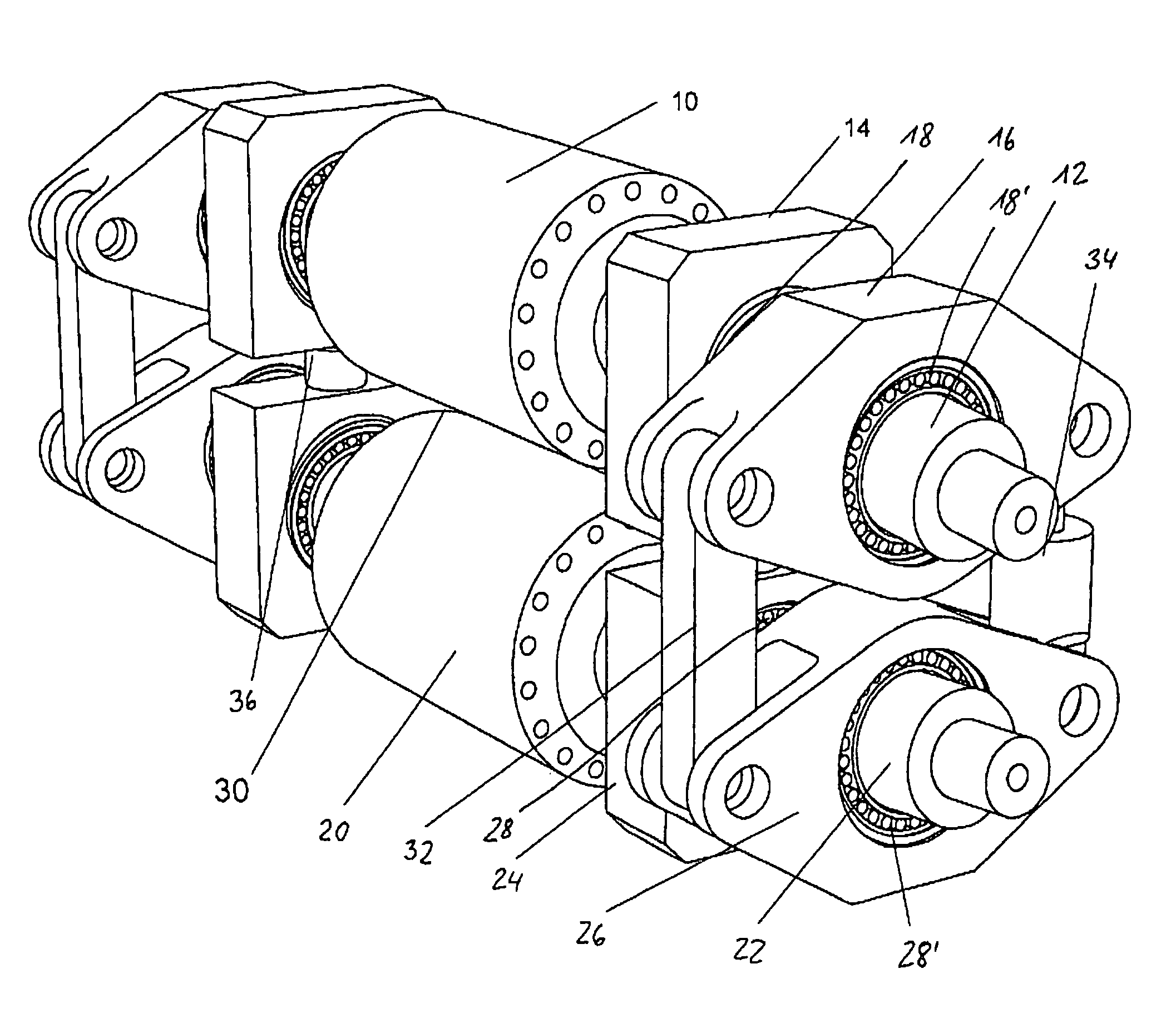
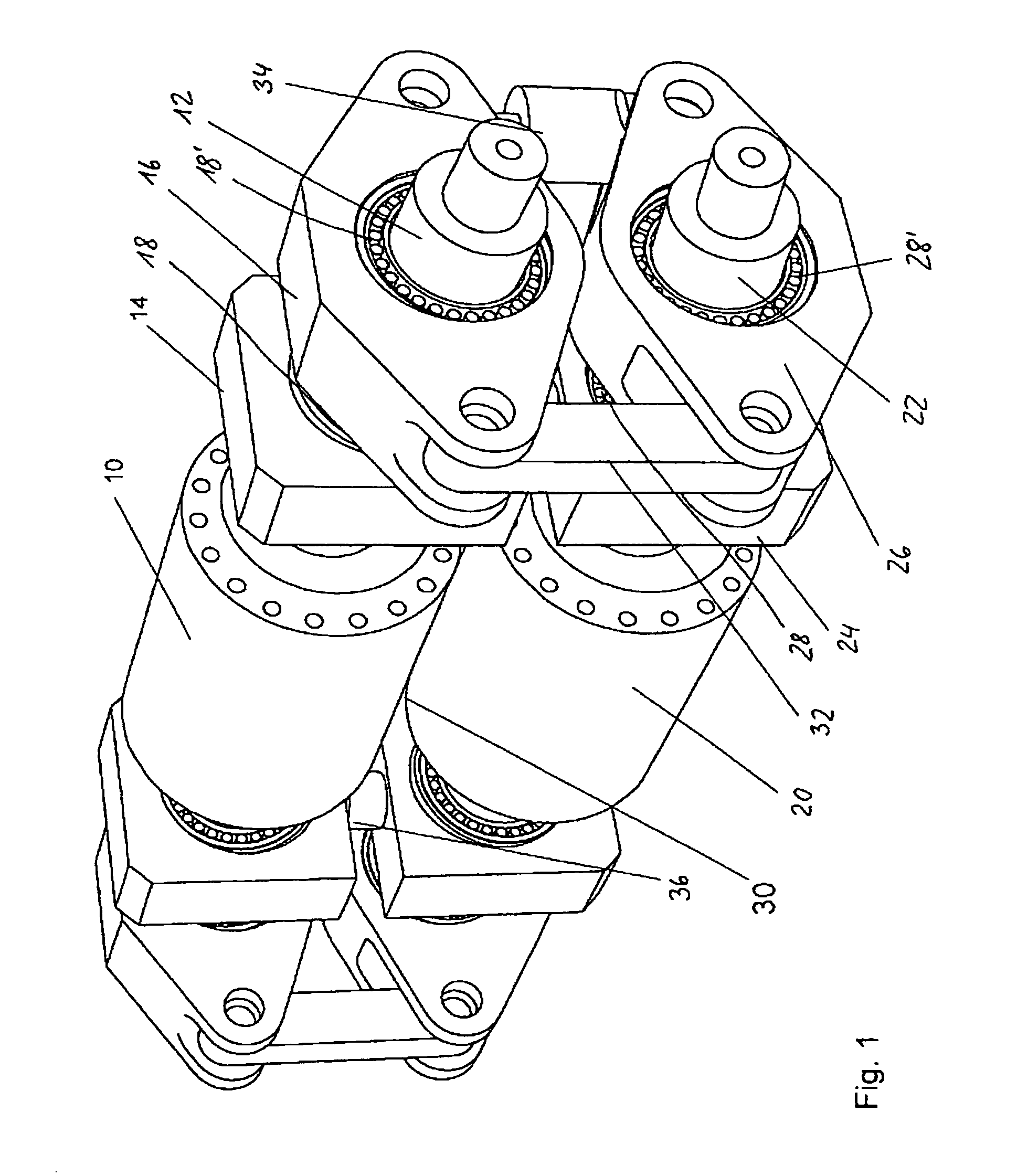
[0024]FIG. 1 shows a perspective view of a roll arrangement having a device for regulating the roll nip according to an embodiment of the present invention. The roll arrangement is symmetrical with reference to a plane which runs perpendicular to the axis of the upper roll 10 and the lower roll 20 so that essentially only that portion of the role arrangement will be described which, starting from this plane, faces the viewer. Arrangement and configuration of the components on the side facing away from the viewer is accordingly chosen and is, due to the mirror-inverted embodiment, not discussed thoroughly in order to avoid repetitions.

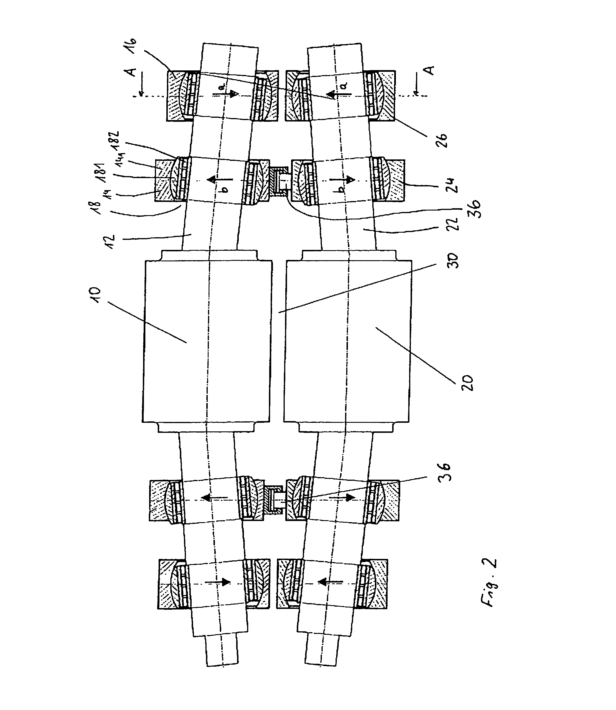
[0025]The roll arrangement of FIG. 1 comprises a roll consisting of an upper roll and a lower roll 20, wherein a roll nip is formed therebetween. Upper roll 10 comprises two axially diametrically opposed roll journals 12 which are respectively received within two bearing blocks 18, 18′ which will be further described in connection with FIG. 2. The inner...


PUM


Abstract

A compact roll arrangement has a device and method for regulating the roll nip so that intermittently coated films may be calendared precisely. A bearing block is arranged in a bearing jewel, and first lever arms of the clamping latch of the upper roll and the lower roll are connected rigidly to one another. Bearing jewels which lie opposite to one another, of the upper roll and the lower roll are connected to one another via a second actuating element. A controller acts on first and second actuating elements, so that the first actuating elements are moved to adjust the roll nip according to a predetermined thrust and a predetermined linear load, and the second actuating elements are moved to maintain the bearing jewels in a relative rest position which is defined by specified densification of a material web passing the roll nip.

Description

BACKGROUND OF THE INVENTION[0001]The invention relates to a roll arrangement having a device for regulating the roll nip, comprising a roll pair which consists of an upper roll and a lower roll, between which a roll nip is formed, wherein each roll is provided with two roll journals which lie axially diametrically opposite one another, at least two bearing blocks for each roll journal, wherein one or more bearings are received in a bearing block, and a bearing block which lies in each case on the outside on the roll journal, in a clamping latch which has a first lever arm and a second lever arm, wherein the second lever arm of the respective clamping latch of the upper roll and the second lever arm of the respective clamping latch of the lower roll are connected to one another via a first actuating element, mutually corresponding bearing jewels and clamping latches of the upper roll and the lower roll lie opposite one another, and a controller which acts on the first and the second ...

Claims


Application Information

Patent Timeline
IPC IPC(8): B21B37/62B21B31/32B21B37/38B21B31/07B21B31/02B21B31/04B21B37/64H01M4/04H01M4/66H01M10/0525
CPCB21B37/62B21B31/07B21B31/04B21B31/32B21B37/38B21B37/64H01M4/0435H01M10/0525B21B31/02B21B31/028H01M4/662Y02E60/10
Inventor HACKFORT, THOMASWOLTERS, KAYWITTEBROCK, HEINZGOTTSZKY, JOERG
Owner SCHAWK USA
Learn More