Turbine rotor comprising a ventilation spacer

Active Publication Date: 2019-03-21
SN DETUDE & DE CONSTR DE MOTEURS DAVIATION S N E C M A
View PDF7 Cites 3 Cited by
  • Summary
  • Abstract
  • Description
  • Claims
  • Application Information

AI Technical Summary

Benefits of technology

[0016]One objective of the invention is therefore to propose a ventilation system of an element such as a low-pressure turbine of a machine, which does not reduce the li

Problems solved by technology

It turns out, however, that their production is painstaking and cannot be accurately controlled, so that it is necessary to over-dimension them so as to guarantee a minimum cross-section for ventilating the bottoms of the sockets.
At present there also does not exist a simple and reliable means of control allowing verification that the cross section of the lunules is sufficient for correctly ventilating the disks.
However, the quantity of

Method used


Image

  • Turbine rotor comprising a ventilation spacer
  • Turbine rotor comprising a ventilation spacer
  • Turbine rotor comprising a ventilation spacer

Examples


Example

[0059]As illustrated in FIG. 6, in a first embodiment the spacer 40 can be discontinuous and comprise several subparts 40′ which are individually attached between the internal radial flange 22 of the sealing ring 20 and the hub 31, typically at each bolting point. In this case, the subparts 40′ are attached so as to provide a space E between two adjacent subparts 40′, said spaces E defining the passages 42 for the injection of the cooling fluid F from the radially internal cavity 8 into the ventilation cavity 9. The sub parts 40′ can have identical shapes and sizes, or as a variant be distinct so as to adjust, on a case by case basis, the desired ventilation flow rates.

Example

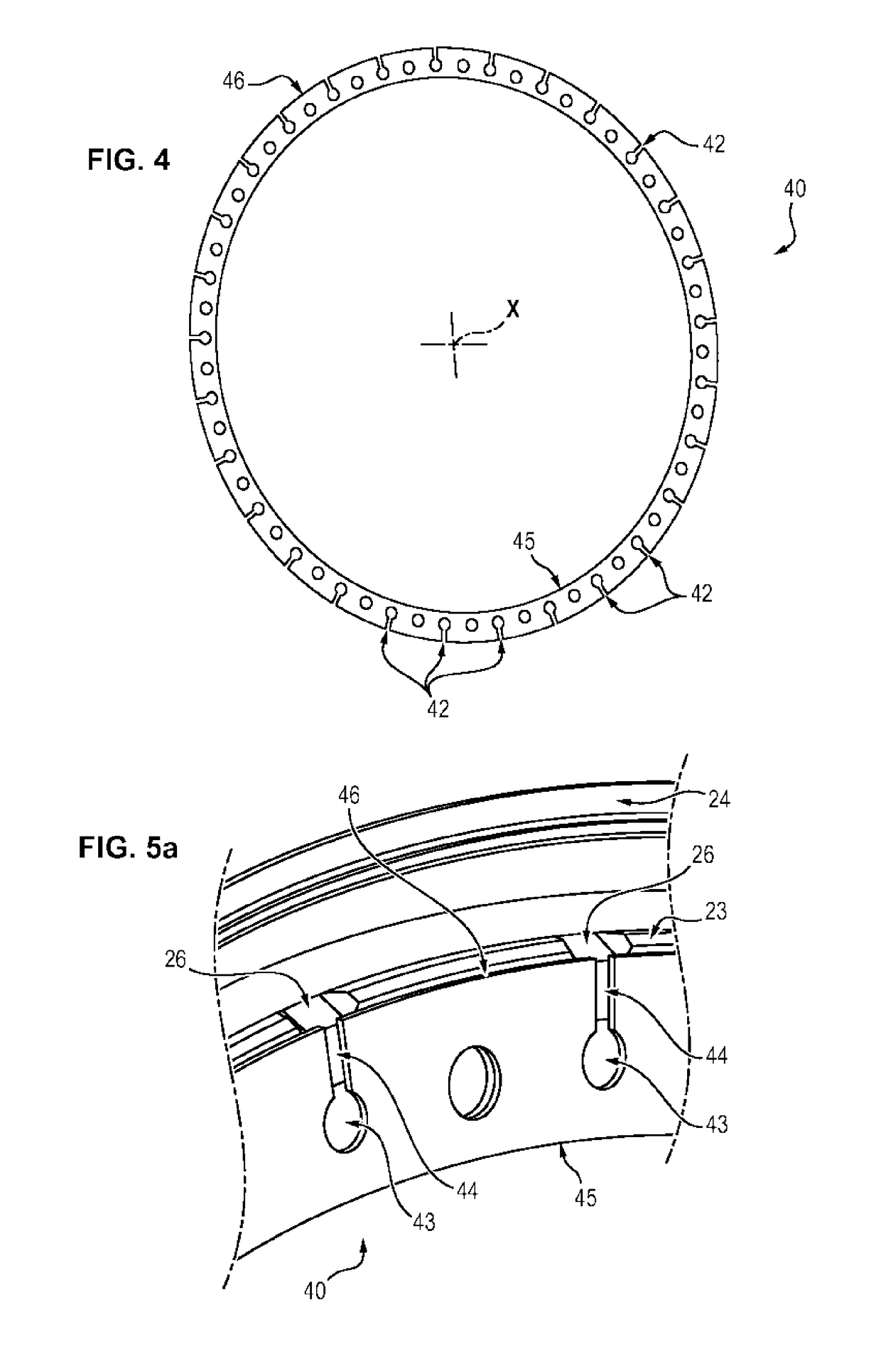
[0060]As a variant, in a second embodiment illustrated in FIG. 4, the spacer 40 can be continuous, i.e. a single part and, if appropriate, formed as a single piece (as illustrated in particular in FIGS. 4, 5a and 5b). In this case, the passages 42 are formed in the spacer 40, for example by machining, drilling, etc.

[0061]Each passage 42 can comprise, as illustrated in FIG. 5a, an axial through opening 43, formed in the spacer 40 and leading into the internal cavity 8, i.e. at the hub 31 and at a distance (radially toward the axis X of the rotor) from the ventilation cavity 9, and a groove 44, extending substantially radially with respect to the axis X from the opening 43 and leading into the ventilation cavity 9.

[0062]More precisely, the spacer 40 comprises a radially external edge 46 leading into the ventilation cavity 9 and a radially internal edge 45 leading into the internal cavity 8, at the hub 31. The through openings 43 are then formed at a distance from the two edges 45, 46 ...


PUM


Abstract

A rotor of a member of a turbomachine, for example a rotor of a turbine, the rotor including a first element, a second element defining with the first element a ventilation cavity, the rotor including a spacer that is introduced and secured between the first element and the second element and that includes a row of through-passages that are configured to permit injection of cooling fluid into the ventilation cavity.

Description

FIELD OF THE INVENTION[0001]The invention relates generally to gas turbine engines, and more particularly to the ventilation of the stages of a turbine, for example a low-pressure turbine of a turbomachine. Fields of application of the invention are aircraft turbojets and turboprops and industrial gas turbines.TECHNICAL BACKGROUND[0002]One example of a turbomachine is illustrated in FIG. 1.[0003]A turbomachine 1 typically comprises a nacelle which forms an opening for the admission of a predetermined flow of air to the engine itself. Conventionally, the gases flow from upstream to downstream through the turbomachine.[0004]Generally, the turbomachine comprises one or more sections 4 for compressing the air admitted into the engine (generally a low-pressure section and a high-pressure section). The air thus compressed is admitted into the combustion chamber 5 and mixed with fuel before being burned there.[0005]The hot combustion gases originating from this combustion are then expanded...

Claims


Application Information

Patent Timeline
IPC IPC(8): F01D5/08F01D5/06F01D11/02
CPCF01D5/082F01D5/066F01D5/088F01D11/02F05D2260/20F05D2260/31Y02T50/60
Inventor OUDIN, BENJAMIN CYRILLE JACQUESCASALIGGI, PASCALCAPOLUNGO, THIERRY LAURENTPASQUIET, DIDIER DESIR RENE
Owner SN DETUDE & DE CONSTR DE MOTEURS DAVIATION S N E C M A
Why Eureka
Try Eureka