Projector and control method therefor

a technology of projectors and control methods, applied in the field of projectors, can solve the problems of poor versatility of techniques, limited use scenes, and no description of specific methods

Active Publication Date: 2015-10-13
SEIKO EPSON CORP
View PDF9 Cites 25 Cited by
  • Summary
  • Abstract
  • Description
  • Claims
  • Application Information

AI Technical Summary

Benefits of technology

[0009]An advantage of some aspects of the invention is to solve at least the problems described above, and the invention can be implemented as the following application examples or forms.

Problems solved by technology

Therefore, a scene of usage is limited.
In particular, in ordinary homes, many families do not own the projector itself and do not have an opportunity for using the technique.
Therefore, versatility of the technique is poor.
However, there is no description concerning a specific method, for example, in what kinds of situations the two functions are switched (properly used).
Therefore, it is difficult to effectively utilize the two functions.

Method used


Image

  • Projector and control method therefor
  • Projector and control method therefor
  • Projector and control method therefor

Examples


first embodiment

Overview of a Projector Usage Scene

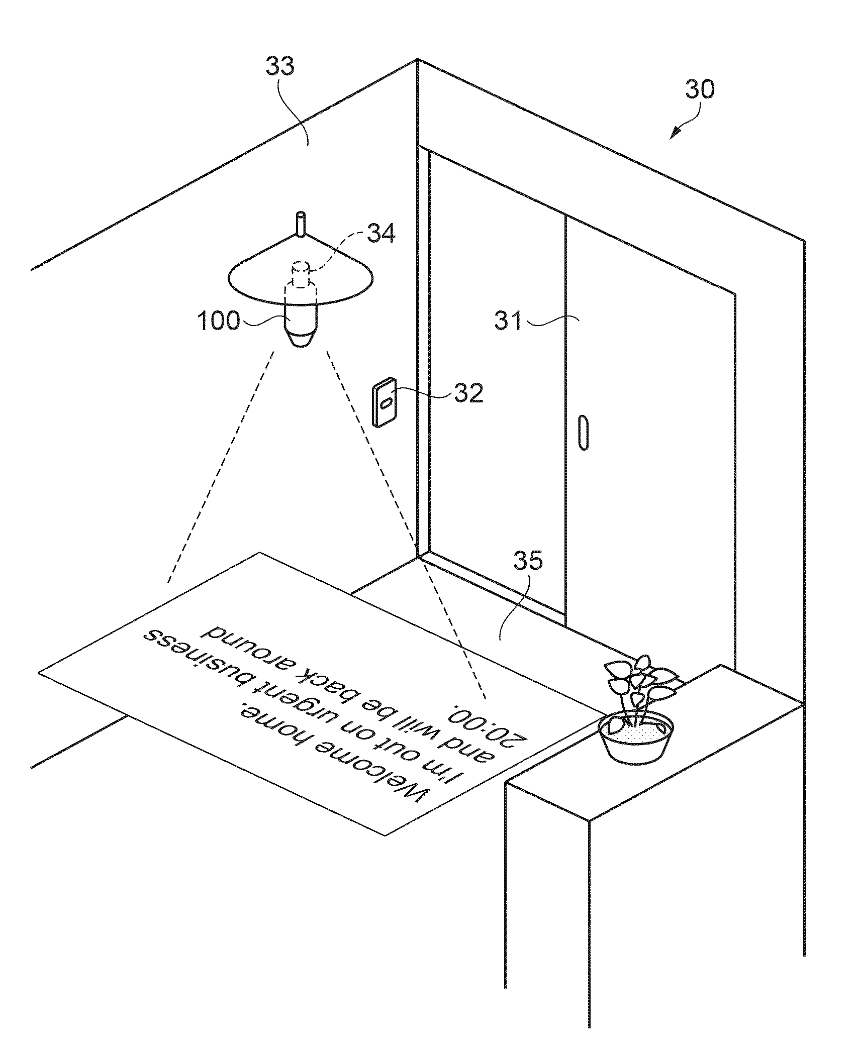
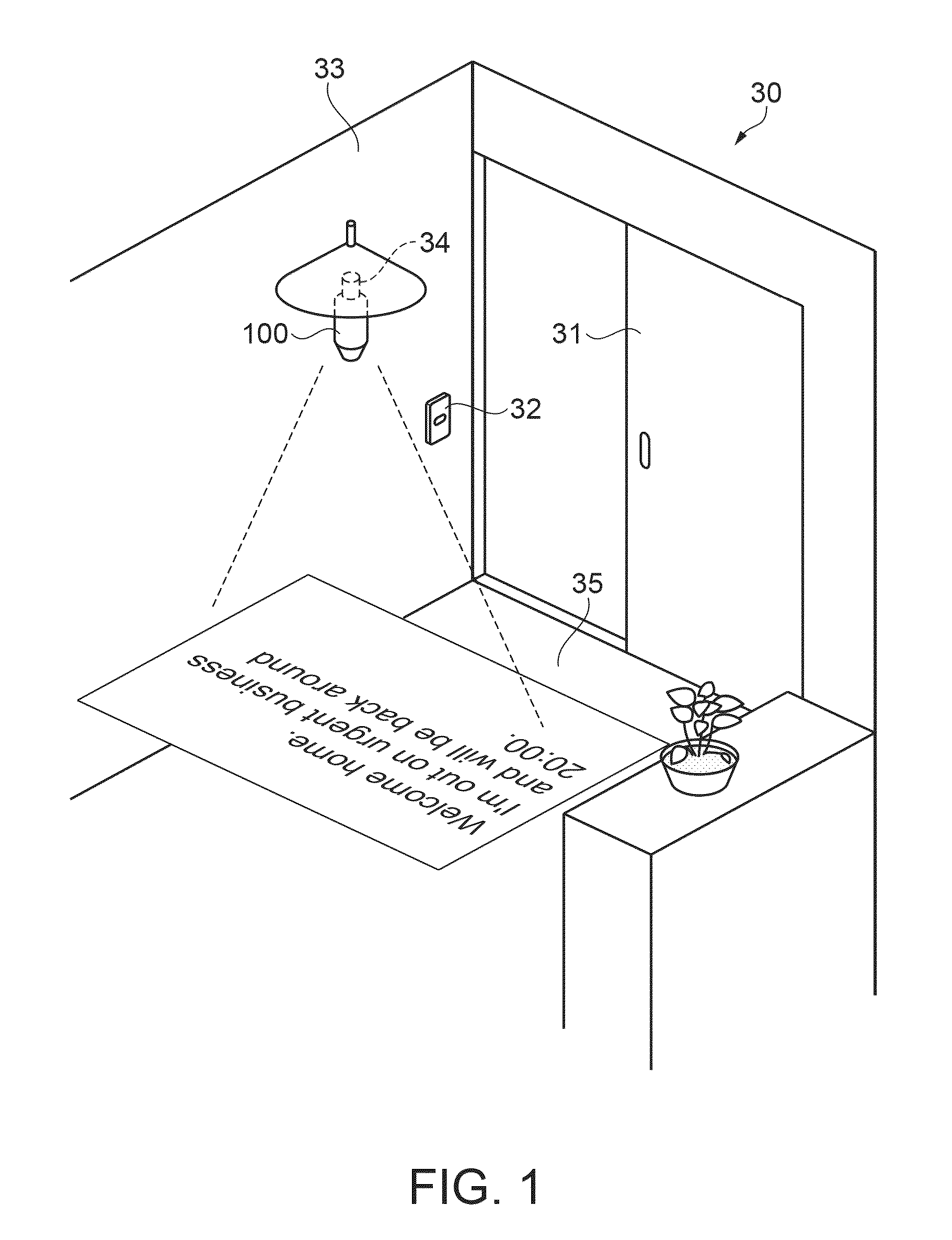
[0037]FIG. 1 is a diagram of a form of a usage scene of a projector according to a first embodiment. First, an example of a usage scene of a projector 100 according to this embodiment is explained.

[0038]The projector 100 is a projector that can be attached to a socket for illumination set in an ordinal home. In the example shown in FIG. 1, a connecting unit (a plug) of the projector 100 is fixed to a socket 34 for lighting equipment (a lighting fixture) set on a ceiling 33 of an entrance hall 30. The projector 100 can switch an illumination mode in which the projector 100 functions as the lighting equipment (the lighting fixture) and a projection mode in which the projector 100 functions as a projector. A specific configuration, a switching method for the two modes, and the like are explained below.

[0039]FIG. 1 shows a situation in which, when a family member returns to the house where the family is out at night, the family member turns on an illum...

second embodiment

[0109]FIG. 8 is a flowchart for explaining a flow of a control method according to a second embodiment. The second embodiment is different from the first embodiment in a part of the control method for the projector 100. The configuration of the projector 100 is the same as the configuration in the first embodiment. In the control method according to this embodiment, a part of the control method according to the first embodiment (FIG. 4) is changed. Therefore, redundant explanation concerning common processing operations and the like is omitted. As in the first embodiment, an operation flow shown in FIG. 8 is executed by the control unit 10 controlling the units of the projector 100 including the communication unit 12 on the basis of the driving program stored in the storing unit 19.

[0110]The control method according to this embodiment is effective for timely informing a user that a message (content) is received when it takes time to read data, for example, when it is desired to disp...

modification 1

[0136]FIGS. 10A and 10B are diagrams showing forms of images in the illumination mode.

[0137]In the embodiments, as an example of the image signal in the illumination mode, the image signal specifying the plain image is explained. However, an image is not limited to this configuration. Various images (hereinafter, “illumination images”) can be used.

[0138]For example, like an illumination image 60 shown in FIG. 10A, the image may be an image in which a plurality of circles having different tones are concentrically arranged in the center of an external shape (substantially coinciding with the display surface of the spatial-light modulating device 3) of an image formed in a laterally long rectangular shape. Specifically, a circle 61 in the center has the highest tone (white: 255 tone), the tone gradually decreases toward the outer side, and the tone is the lowest (black: 0 tone) in the peripheral edge of the rectangular shape (hereinafter referred to as “concentric image”). In other wor...


PUM

PropertyMeasurementUnit
repetition frequencyaaaaaaaaaa
electric poweraaaaaaaaaa

Abstract

A projector can be easily attached by mounting a connecting unit to a socket for illumination in an ordinary home. Since the projector includes a communication unit configured to receive an electronic mail, the projector updates an image signal and adjusts a diffusion degree of modulated light by a light-diffusion adjusting unit on the basis of contents of the mail received by the communication unit. Therefore, when a user desires to inform family members who will return home that the user suddenly has to go out, if the user transmits in advance, to the projector, a mail including a message for a family member who returns home, the family member who returns home turns on an illumination switch at the entrance, whereby the projector can start up, perform an illuminating function, and clearly project and display the message.

Description

[0001]The entire disclosure of Japanese Patent Application No. 2012-162387, filed Jul. 23, 2012 is expressly incorporated by reference herein.BACKGROUND[0002]1. Technical Field[0003]The present invention relates to a projector that can function as lighting equipment and a control method for the projector.[0004]2. Related Art[0005]In a company, a public office, or the like, staff members often hold a meeting for a large number of people while projecting materials on a wall surface or the like of a meeting room using a projector. In such a meeting, for example, when data of a prepared material is wrong, the staff members sometimes desire to replace the material in a hurry. For example, JP-A-2009-3356 (Patent Literature 1) discloses a technique suitable for such a situation. Specifically, a receiving function or the like is added to the projector, whereby, when an emergent electronic mail is received, a material attached to the electronic mail is projected instead of a projected materi...

Claims


Application Information

Patent Timeline
Patent Type & Authority Patents(United States)
IPC IPC(8): G03B21/28H04L12/28G02F1/1334H04N9/31G02B5/32G02F1/1335
CPCG02F1/13342H04L12/2818H04N9/31H04N9/3111H04N9/317H04L2012/285G02B5/32G02F1/133621G03B21/28G02F1/13347F21V33/0052G02F1/1334H04N9/3155H04N9/3179
Inventor KINEBUCHI, TADASHIYAMAGUCHI, KAORU
Owner SEIKO EPSON CORP
Why Eureka
Try Eureka