
Load compensation in RF amplifiers

a technology of rf amplifier and load compensation, which is applied in the direction of amplifiers, amplifiers with semiconductor devices/discharge tubes, amplifiers, etc., can solve problems such as the impact of the operation of rf amplifiers

Active Publication Date: 2015-10-13
PSEMI CORP
View PDF14 Cites 31 Cited by
  • Summary
  • Abstract
  • Description
  • Claims
  • Application Information

AI Technical Summary

Benefits of technology

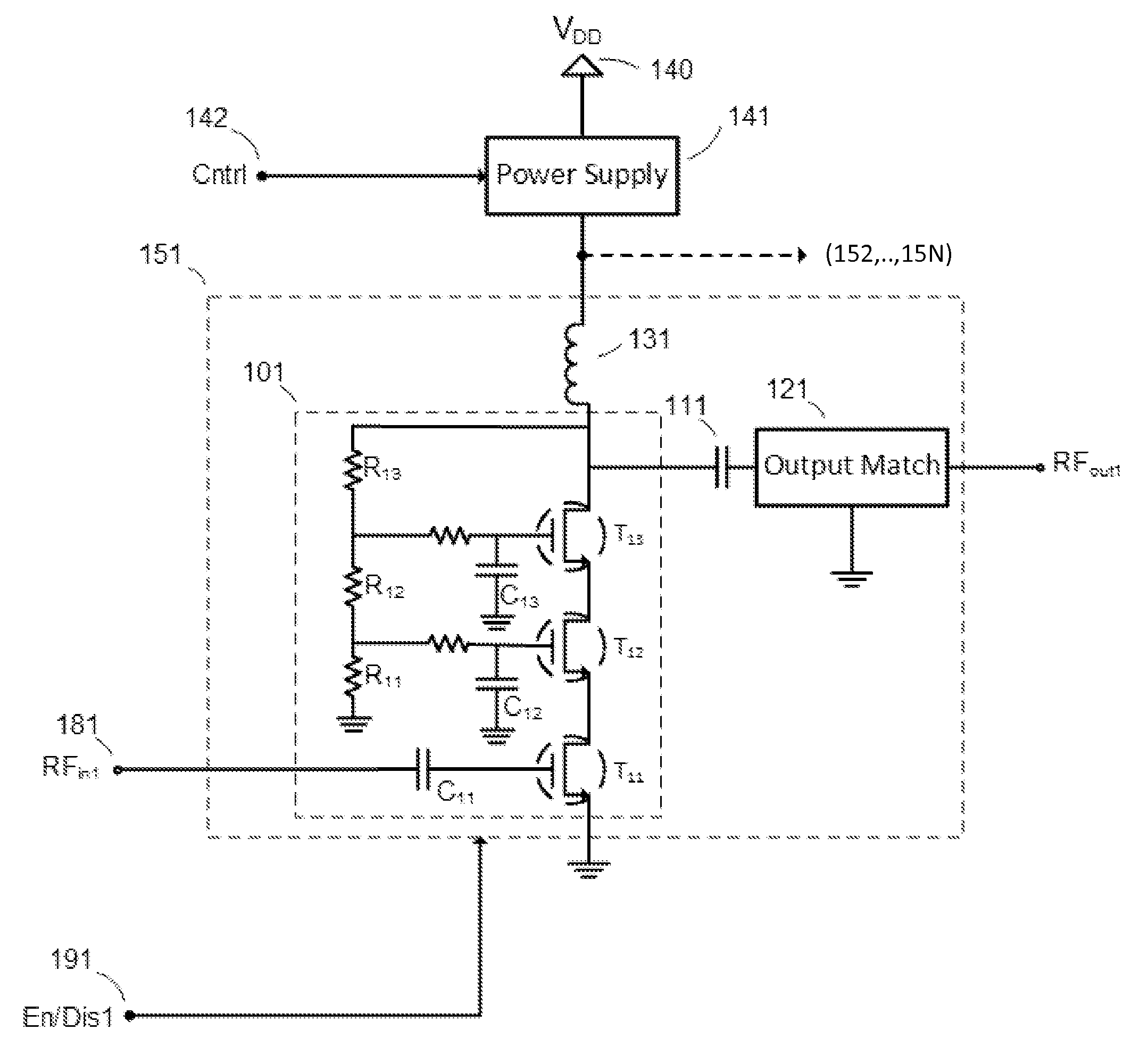
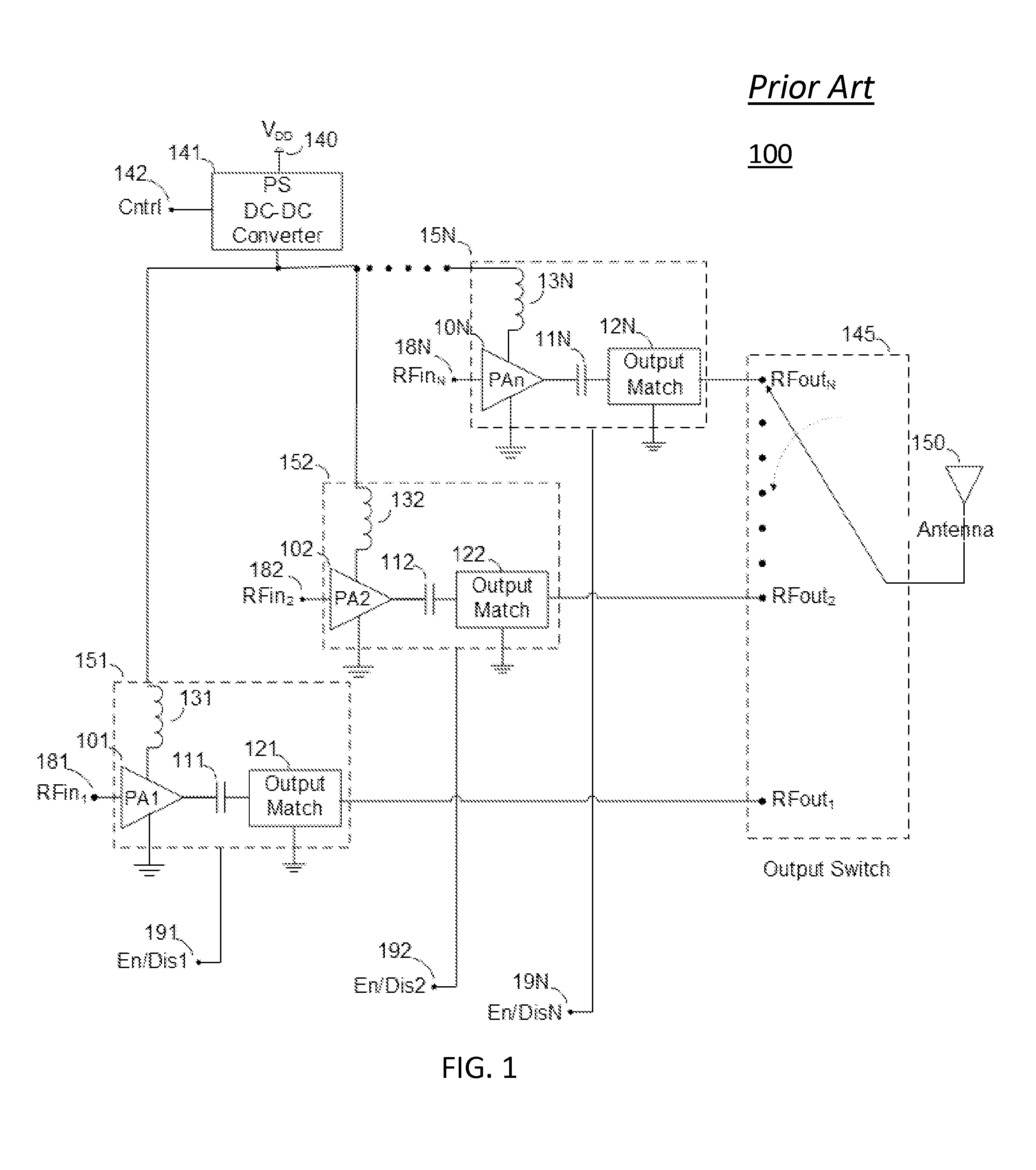
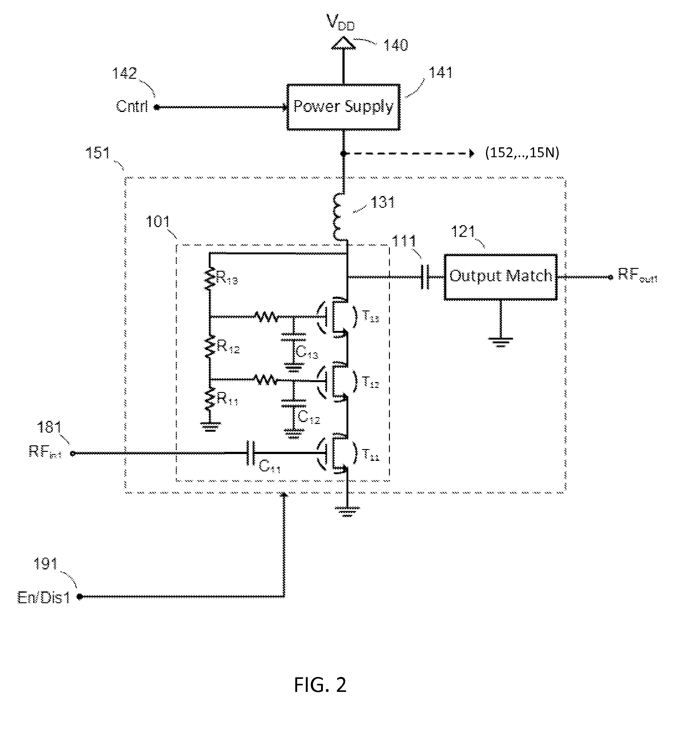
[0007]According to a third aspect of the present disclosure, a method for reducing loading of a power supply unit in a multi-mode and / or multi-band power amplifier arrangement is presented, the method comprising: providing a power supply unit; providing a plurality of power amplifier units; connecting the plurality of power amplifier units to a common output port of the power supply unit; selecting a band and / or mode of operation of the amplifier arrangement; based on the selecting, activating a corresponding power amplifier unit of the plurality of power amplifier units; based on the selecting, deactivating one or more power amplifier units of the plurality of power amplifier units; based on the deactivating, decoupling the one or more deactivated power amplifier units from the power supply unit, and based on the decoupling, reducing a loading effect of the one or more deactivated power amplifier units on the power supply unit.

Problems solved by technology

Such residual loading can affect the supply provided to a turned ON RF amplifier and thereby impact operation of the ON RF amplifier.

Method used


Image

  • Load compensation in RF amplifiers
  • Load compensation in RF amplifiers
  • Load compensation in RF amplifiers

Examples


Embodiment Construction

[0019]Throughout this description, embodiments and variations are described for the purpose of illustrating uses and implementations of the inventive concept. The illustrative description should be understood as presenting examples of the inventive concept, rather than as limiting the scope of the concept as disclosed herein.

[0020]As used in the present disclosure, the terms “switch ON”, “turn ON” and “activate” may be used interchangeably and can refer to making a particular circuit element electronically operational.

[0021]As used in the present disclosure, the terms “switch OFF”, “turn OFF” and “deactivate” may be used interchangeably and can refer to making a particular circuit element electronically non-operational.

[0022]As used in the present disclosure, the terms “amplifier” and “power amplifier” may be used interchangeably and can refer to a device that is configured to amplify a signal input to the device to produce an output signal of greater magnitude than the magnitude of...


PUM


Abstract

Methods and systems for reducing parasitic loading on a power supply output in RF amplifier arrangements used in multiband and / or multitude RF circuits are presented. Such RF circuits can comprise a plurality of RF amplifiers of which only one is activated for a given desired transmission mode and / or band.

Description

BACKGROUND[0001]1. Field[0002]The present teachings relate to radio-frequency (RF) amplifiers used in RF circuits. More particularly, the present teachings relate to methods and systems for reducing parasitic loading, such as for example stray capacitance, in RF amplifiers used in multiband and multimode RF circuits.[0003]2. Description of Related Art[0004]In an effort to cover the many communication standards and frequency bands used in today's data and voice transmissions, RF circuits used in today's mobile devices are designed with multiple RF amplifiers (e.g. a power amplifier (PA)) each tailored to a specific communication standard and frequency band. During typical operation of the device (e.g. mobile handset, tablet) only one of the multiple RF amplifiers is activated (e.g. turned ON) and used for transmission of a signal, and the unused RF amplifiers are deactivated (e.g. turned OFF). A turned OFF RF amplifier can exhibit a residual loading, such as a stray capacitance, with...

Claims


Application Information

Patent Timeline
Patent Type & Authority Patents(United States)
IPC IPC(8): H03F1/14H03F3/68H03F3/189H03F3/20
CPCH03F3/68H03F3/20H03F3/189H03F1/0277H03F1/223H03F3/193H03F3/211H03F3/245H03F2200/111H03F2203/21145
Inventor OLSON, CHRISNOBBE, DAN WILLIAMDYKSTRA, JEFFREY A.
Owner PSEMI CORP
Learn More