Needle and guidewire holder

a technology of guidewire and needle, which is applied in the field of needle and guidewire holder, can solve the problems of difficulty in performing angioplasty, inability to penetrate the proximal cap of the plaque with the guidewire, and failure to achieve revascularization up to 20% of the time, so as to facilitate needle insertion, prevent hand exposure to radiation, and increase the accuracy of needle puncturing procedur

Active Publication Date: 2015-10-20
SPECTRANETICS
View PDF232 Cites 9 Cited by
  • Summary
  • Abstract
  • Description
  • Claims
  • Application Information

AI Technical Summary

Benefits of technology

[0012]The present invention is directed to a device and a method for needle puncturing of blood vessels for vessel angioplasty. The invention seeks to provide a special needle holder that facilitates needle insertion, and increases the needle puncturing procedure accuracy, while preventing hand exposure to radiation.
[0013]In accordance with an embodiment of the invention, a standard needle is affixed onto a special extended needle holder, e.g., by using a female to male standard luer connection. The needle holder reduces the clinician's hand exposure to x-rays during the needle insertion and provides better control of the needle trajectory and puncture. The device includes a vent for both blood passage to confirm needle tip location in the target artery and for guidewire passage. A standard guidewire may be inserted through the needle into the artery. Afterwards, the needle and needle holder are removed.
[0014]Optionally, a guidewire holding mechanism is provided that reduces procedure time and minimizes blood spillage, by holding the distal portion of the guidewire inside the needle holder.

Problems solved by technology

However, when employing standard angioplasty techniques, angioplasty of BTK arteries fails to achieve revascularization in up to 20% of cases.
The main cause for failure is the inability to penetrate the plaque's proximal cap with the guidewire.
This approach has high success rates, but is technically challenging to perform and has its own complications, especially the danger of vessel perforation.
Puncturing small arteries is not easy; it requires proper manipulation of the C-arm and a gentle needle stick to avoid arterial perforation.
1) Long thin needles are too flexible, which prevents accurate and controlled positioning of the needle tip in the direction of the blood vessel; and
2) Blood is expected to come out from the proximal end of the needle. This is fine for a short needle, but for a long needle the blood may not reach the proximal end due to low blood pressure in the treated vessel and high flow resistance of the long narrow needle lumen.
Another important disadvantage of the prior art, is that during this needle insertion the clinician's hand is exposed to direct X-ray radiation which may have deleterious long-term health effects.

Method used


Image

  • Needle and guidewire holder
  • Needle and guidewire holder

Examples


Embodiment Construction

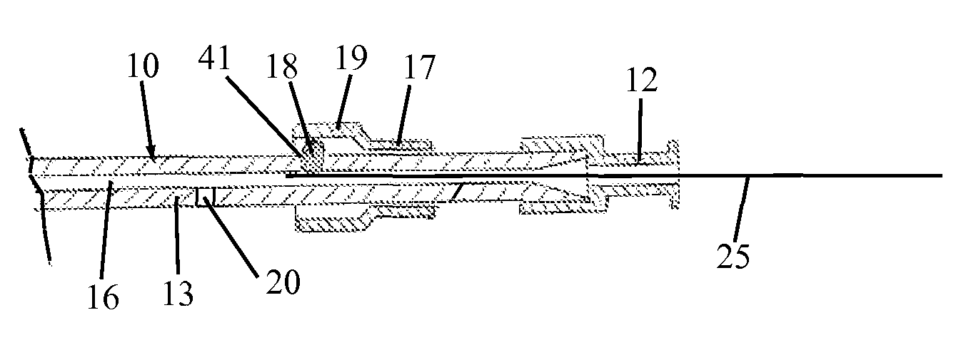
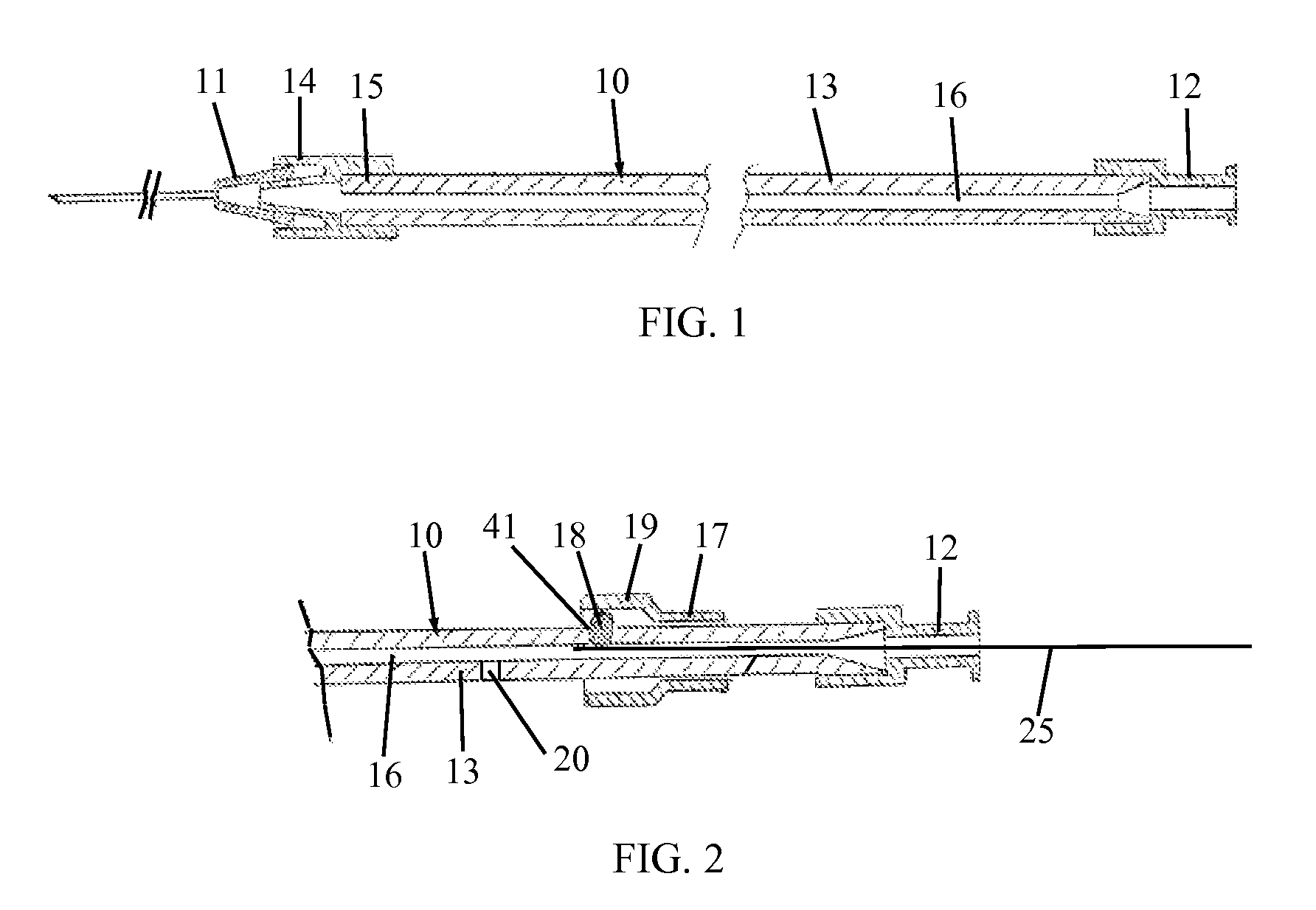
[0018]Reference is now made to FIG. 1, which illustrates a needle holder 10, constructed and operative in accordance with an embodiment of the present invention.

[0019]Needle holder 10 is an elongate stiff member 13 that includes a needle connector 14, such as but not limited to, a male luer connector, at a distal end 15 thereof. Connector 14 connects to a needle 11, such as by means of connecting with a female luer connector affixed to the proximal end of the needle 11. Needle holder 10 may be supplied without the needle 11 and the user connects the holder to the needle. Alternatively, needle holder 10 may be supplied with needle 11 already assembled therewith. Without limitation, needle holder 10 preferably has a length of at least 12 cm, most preferably in the range of 20-25 cm; holder 10 is preferably longer than the needle 11. The elongate stiff member 13 may be a hollow tube with a lumen 16, which may be made, without limitation, from a stiff, clear polymeric material, e.g., po...


PUM


Abstract

Device and method for puncturing blood vessels while using fluoroscopy. The disclosed device enables improved needle orientation control and avoids direct exposure of the clinician's hand to X-ray during the puncturing procedure.

Description

CROSS REFERENCE TO RELATED APPLICATIONS[0001]The present application is the United States national phase of International Application No. PCT / US11 / 64301 filed Dec. 12, 2011 entitled “NEEDLE AND GUIDEWIRE HOLDER,” which claims the benefit of and priority to, under 35 U.S.C. §119(e) and / or 120, U.S. Provisional Application Ser. No. 61 / 516,906 filed Apr. 11, 2011 entitled “DEVICE AND METHOD FOR BTK BLOOD VESSEL TREATMENT,” and U.S. Provisional Application Ser. No. 61 / 571,856 filed Jul. 7, 2011 entitled “NEEDLE-HOLDER FOR BLOOD VESSELS PUNCTURE,” and U.S. Provisional Application Ser. No. 61 / 575,160 filed Aug. 17, 2011 entitled “DEVICE AND METHOD FOR GUIDEWIRES CAPTURING,” and U.S. Provisional Application Ser. No. 61 / 573,935 filed Sep. 15, 2011 entitled “NEEDLE-HOLDER WITH INTEGRATED GUIDEWIRE HOLDER FOR BLOOD VESSELS PUNCTURE,” and U.S. Provisional Application Ser. No. 61 / 626,183 filed Sep. 22, 2011 entitled “HYPO-TUBE BASED SUPPORT CATHETER,” each of which is hereby incorporated herein...

Claims


Application Information

Patent Timeline
Patent Type & Authority Patents(United States)
IPC IPC(8): A61M5/14A61B17/221A61M25/00A61M25/09A61M25/06A61B17/22
CPCA61B17/22A61B17/221A61M25/0054A61M25/065A61M25/09041A61M25/0606A61B2017/22001A61B2017/22035A61B2017/22038A61B2017/22069A61B2017/22094A61M2025/09116A61M2025/09125A61B17/3207A61B2017/00367A61B2017/00477A61B2017/320052A61B6/12
Inventor ROTTENBERG, DANSACHER, RONEN
Owner SPECTRANETICS
Why Eureka
Try Eureka