Power control device and power control method

a power control device and power control technology, applied in the direction of battery/cell propulsion, process and machine control, instruments, etc., can solve the problem of limited power range that allows charging of electromotive vehicles, and achieve the effect of controlling electric power supplied minutely

Inactive Publication Date: 2015-10-20
TOYOTA JIDOSHA KK
View PDF7 Cites 3 Cited by
  • Summary
  • Abstract
  • Description
  • Claims
  • Application Information

AI Technical Summary

Benefits of technology

[0017]According to the aspects of the invention, it is possible to minutely control electric power supplied from an external power supply to a vehicle using a signal generated by the external power supply.

Problems solved by technology

Particularly, the range of information that is transmittable by a signal transmitted from the external power supply to the electromotive vehicle (for example, the range of allowable current value of the external power supply, which is transmittable by a pilot signal) is limited to a value that falls within a predetermined range because of the specifications of the signal or the physical requirements of the external power supply.
Therefore, there is a problem that a power range that allows control for charging the electromotive vehicle is limited.

Method used


Image

  • Power control device and power control method
  • Power control device and power control method
  • Power control device and power control method

Examples


first embodiment

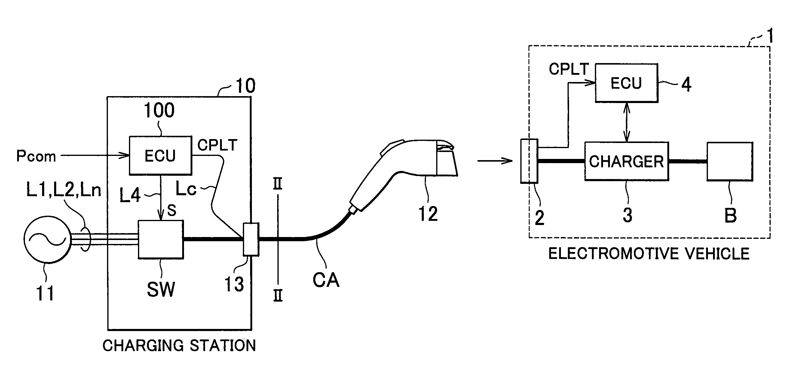
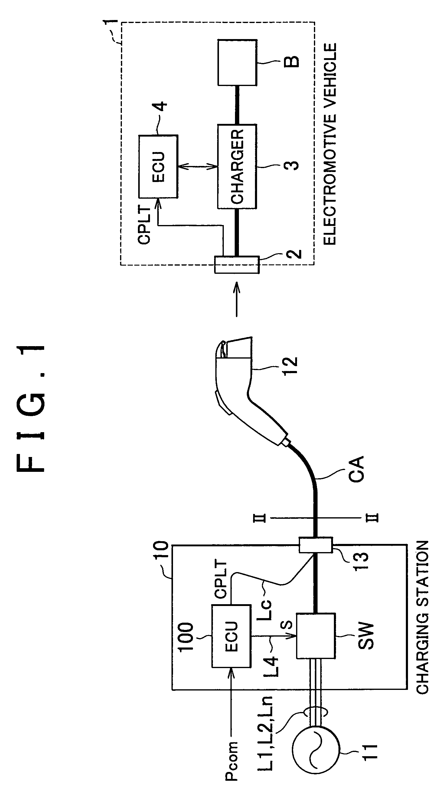
[0032]FIG. 1 is a schematic view of a charging station 10 that is equipped with a power control device according to a first embodiment of the invention. The charging station 10 is an alternating-current power supply that is exclusively provided in order to charge an electrical storage device equipped for an electromotive vehicle, such as a vehicle 1. Note that the charging station 10 may be a direct-current power supply.

[0033]The vehicle 1 is an electromotive vehicle that is propelled by a motor (not shown) driven by electric power of an electrical storage device B. The vehicle 1 may be an electric vehicle that includes only a motor as a driving source or may be a hybrid electric vehicle that includes a motor and an engine.

[0034]The vehicle 1 is a so-called plug-in vehicle, and includes a charging system for charging the electrical storage device B with alternating-current power supplied from the external charging station 10. The charging system includes an inlet 2, a charger 3 and ...

embodiment to first embodiment

Alternative Embodiment to First Embodiment

[0076]In the above described first embodiment, the upper limit value (current capacity) of the supply current is 12 amperes; however, the upper limit of the supply current may be larger than 12 amperes.

[0077]FIG. 9 shows a first map when the upper limit value of the supply current is 20 amperes. Note that, in FIG. 9, the voltage V1, the voltage V2 and the lower limit value of supply current are respectively 100 volts, 200 volts and 6 amperes as in the case of the first embodiment.

[0078]In this case, the electric power value P1max is set to 2 kilowatts (which is equal to 100 volts multiplied by 20 amperes), the electric power value P2min is 1.2 kilowatts (which is equal to 200 volts multiplied by 6 amperes), the electric power value P2min is smaller than the electric power value P1max, and the threshold Pb is set to 1.2 kilowatts that is the electric power value P2min.

[0079]That is, when the electric power command value Pcom falls within the ...

second embodiment

[0080]In the first embodiment, the case where the supply voltage is set to any one of the two voltages V1 and V2 is described. In contrast to this, in a second embodiment, the case where the supply voltage is set to any one of three voltages V1, V2 and V3 will be described.

[0081]FIG. 10 is a schematic view of a charging station 10a that includes a power control device according to the second embodiment.

[0082]The charging station 10a includes a commercial power supply 11a, a switching device SWa, a charging cable CAa and an ECU 100a.

[0083]The commercial power supply 11a is a so-called three-phase four-wire system alternating-current power supply that is widely used in Europe, and the like. The commercial power supply 11a and the switching device SWa are connected by power lines Lu, Lv, Lw and a neutral line Ln. U-phase, V-phase and W-phase alternating-current powers are respectively supplied to the power lines Lu, Lv and Lw. The potential difference (phase voltage) between each of t...


PUM


Abstract

A power control device that controls electric power supplied from an external power supply to a vehicle includes: a switching unit that switches a supply voltage value of the external power supply; and a control unit that generates a signal, indicating an allowable current value of the external power supply, to transmit the signal to the vehicle, and that controls the switching unit to thereby control the supply voltage value, wherein the control unit changes the signal and the supply voltage value on the basis of a given electric power command value.

Description

BACKGROUND OF THE INVENTION[0001]1. Field of the Invention[0002]The invention relates to a power control device and power control method that control electric power supplied from an external power supply to a vehicle.[0003]2. Description of the Related Art[0004]An electromotive vehicle, such as an electric vehicle and a hybrid electric vehicle, is in practical use. The electromotive vehicle is propelled by a motor that is driven by electric power stored in an electrical storage device. In addition, in recent years, development of a so-called plug-in vehicle has been proceeding. The plug-in vehicle includes a system that charges an electrical storage device with power supplied from an external power supply called, a charging station, or the like.[0005]In connection with charging control over such a plug-in vehicle, for example, Japanese Patent Application Publication No. 6-245325 (JP-A-6-245325) describes a technique for simplifying charging operation. An electric vehicle described i...

Claims


Application Information

Patent Timeline
Patent Type & Authority Patents(United States)
IPC IPC(8): B60L11/00H02J7/04B60L11/18H02J7/00
CPCB60L11/1838B60L11/1816H02J7/0004H02J7/007H02J7/04Y02T10/7005Y02T90/121Y02T90/128Y02T90/14Y02T90/163Y02T10/7072B60L2210/30B60L2240/547Y04S30/14B60L50/52B60L53/65B60L53/18Y02T10/72Y02T90/12Y02T90/167Y02T10/70H02J7/00036Y02T90/16
Inventor ICHIKAWA, SHINJI
Owner TOYOTA JIDOSHA KK
Why Eureka
Try Eureka