Pressure relief valve

a pressure relief valve and valve body technology, applied in the field of pressure relief valves, can solve the problems of high flow rats in the range of 35,0000 through 45,000 standard cubic feet per minute that cannot be achieved with external pressure relief valves, the helical compression springs of valves are prohibitively large, and certain liquids and gases transported in railway tank cars or tank trucks are particularly hazardous and at elevated temperatures

Active Publication Date: 2015-10-20
KELSO TEHCNOLOGIES INC
View PDF13 Cites 5 Cited by
  • Summary
  • Abstract
  • Description
  • Claims
  • Application Information

AI Technical Summary

Benefits of technology

[0010]Described herein is a pressure relief valve with a valve body with a valve seat that surrounds an aperture within the upper surface of a tank or other container. The valve cover is a square tubular component and protects the valve components within its confines. The valve cover also prevents access to, and tampering, with valve components. The cover bolts (i) attach the valve cover rigidly to spring brackets and (ii) are preferably made of zinc coated carbon steel.
[0016]The spring brackets of the pressure relief valve (i) are preferably A36 or 304 SS steel (ii) attach to the valve flange by welding to (iii) provide a rigid guide for vertical movement of the spring block, to provide a structure for the cover attachment, and to provide a stable rotational axis for the spring drums and spring assemblies. There is also an appended sealing disc that is located between the adjustment screw and the valve body. The valve seal is preferably made from an elastomeric material or a fluoroelastomer. The valve seal provides a tight interface between the valve body seat and the sealing disc to prevent leakage the sealing disk is in its default position, i.e., when the internal pressure of the tank is less than the force exerted by the pre-calibrated spring assemblies.
[0020]The current invention also includes first and second spring bracket braces and each brace is preferably made of A36 carbon steel or 304 SS stainless steel. The spring bracket brace preferably comprises a longitudinal bar which is (i) rectangular in cross-section and (ii) contains a single aperture within each opposing end. The spring bracket brace retains the spring brackets in a parallel position to eliminate binding of the spring block as it rises vertically during the initial valve presetting and during instances when the disc rises from the pressure within the tank or other large closed container. The brace bolt is a socket head cap screw that is preferably made of stainless steel. If there is excessive clearance between the spring block and the spring brackets, the lock and springs may rotate and create friction at the opposing contacting surfaces, and thereby prevent the vertical movement of the spring block.
[0021]The brace bolt retains the spring racket brace rigidly to the spring bracket. The spring brackets are preferably made of A36 steel or 304 SS steel and attach to the valve flange by welding. Spring brackets provide a rigid vertical guide for the vertical movement of the spring block. The spring brackets also attach to the valve cover and thereby provide stable rotational axis for the spring drums and spring assemblies. If there is an excessive clearance between the spring block and the spring brackets, then the spring block and spring brackets may (i) rotate and create friction at their respective contacting surfaces and (ii) thereby prevent the spring block's vertical movement.
[0023]Another object is to provide a constant-force spring pressure relief valve that is reliable, compact and relatively simple in construction and operation.
[0024]Still another object is to provide a constant-force spring pressure relief valve in which the valve disc remains in vertical alignment with the valve seat for maintaining positive shutoff, and prevention of venting of fluids within the tank below a preset pressure.

Problems solved by technology

Unfortunately, in the past high flow rats in the range of 35,0000 through 45,000 standard cubic feet per minute were not achieved with external pressure relief valves.
The problem to overcome was the fact that traditional pressure relief valves comprise helical compression springs that are prohibitively large for high valve flow rates.
Certain liquids and gases transported in railway tank cars or tank trucks are particularly hazardous and at elevated temperatures.
These gases and liquids may expand within the tank and increase the internal pressure within the closed container or tank to a dangerous level.
Unfortunately, size, complexity and cost of the constant-force spring valve required for this particular closed tank application have prevented their general acceptance in the industry.
Space restrictions along the tank or other closed container, as well as design constraints originally limited the number of constant force springs to offset this space and design restriction.
However, with the increased spring assembly force capacity of the current invention, corresponding increased wear and friction would (i) damage these surfaces and (ii) result in a prohibitively high torque requirement to rotate the valve's adjustment screw.

Method used


Image

  • Pressure relief valve
  • Pressure relief valve
  • Pressure relief valve

Examples


Embodiment Construction

I. Structure and Materials of the Preferred Embodiment and Other Embodiments

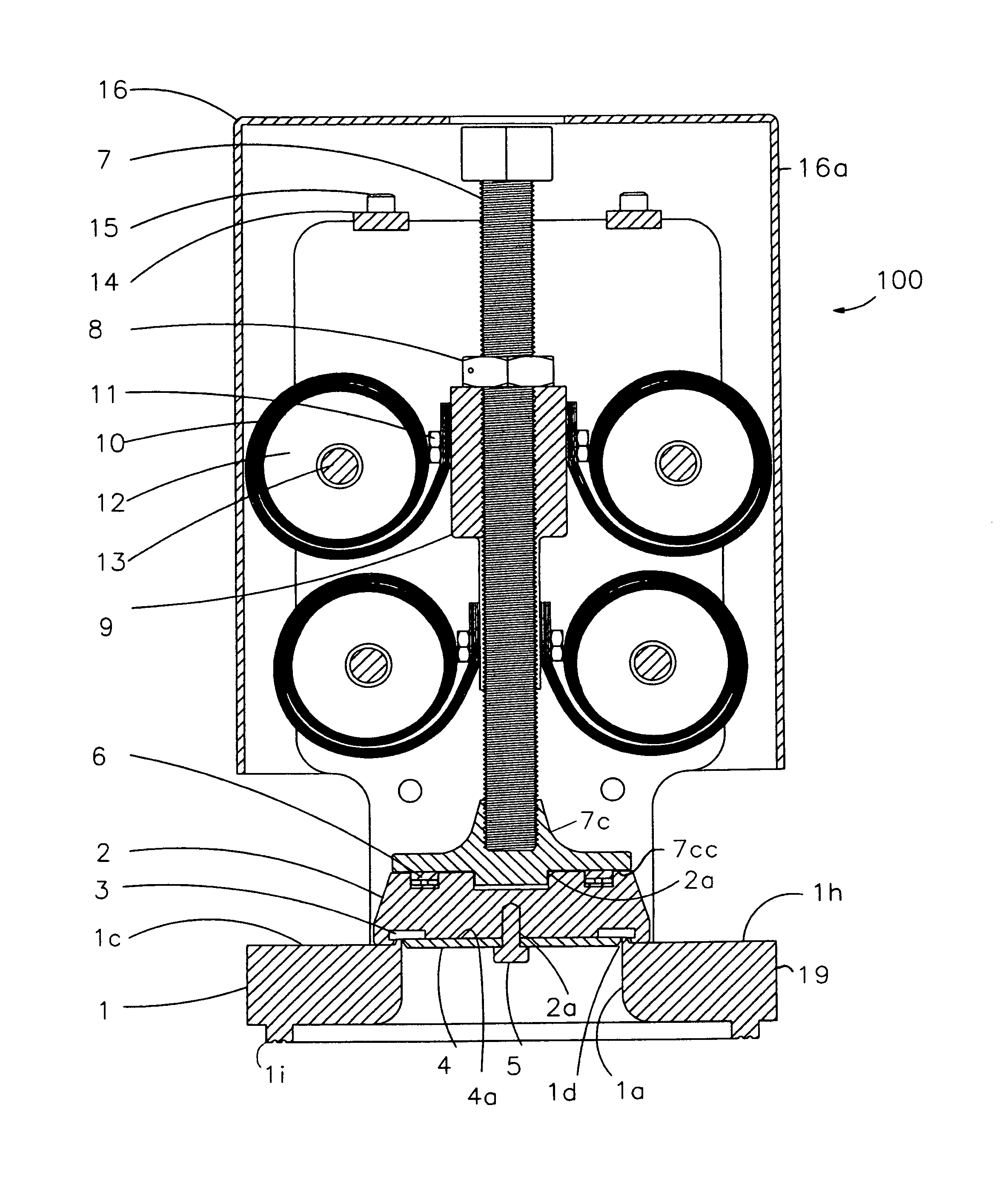
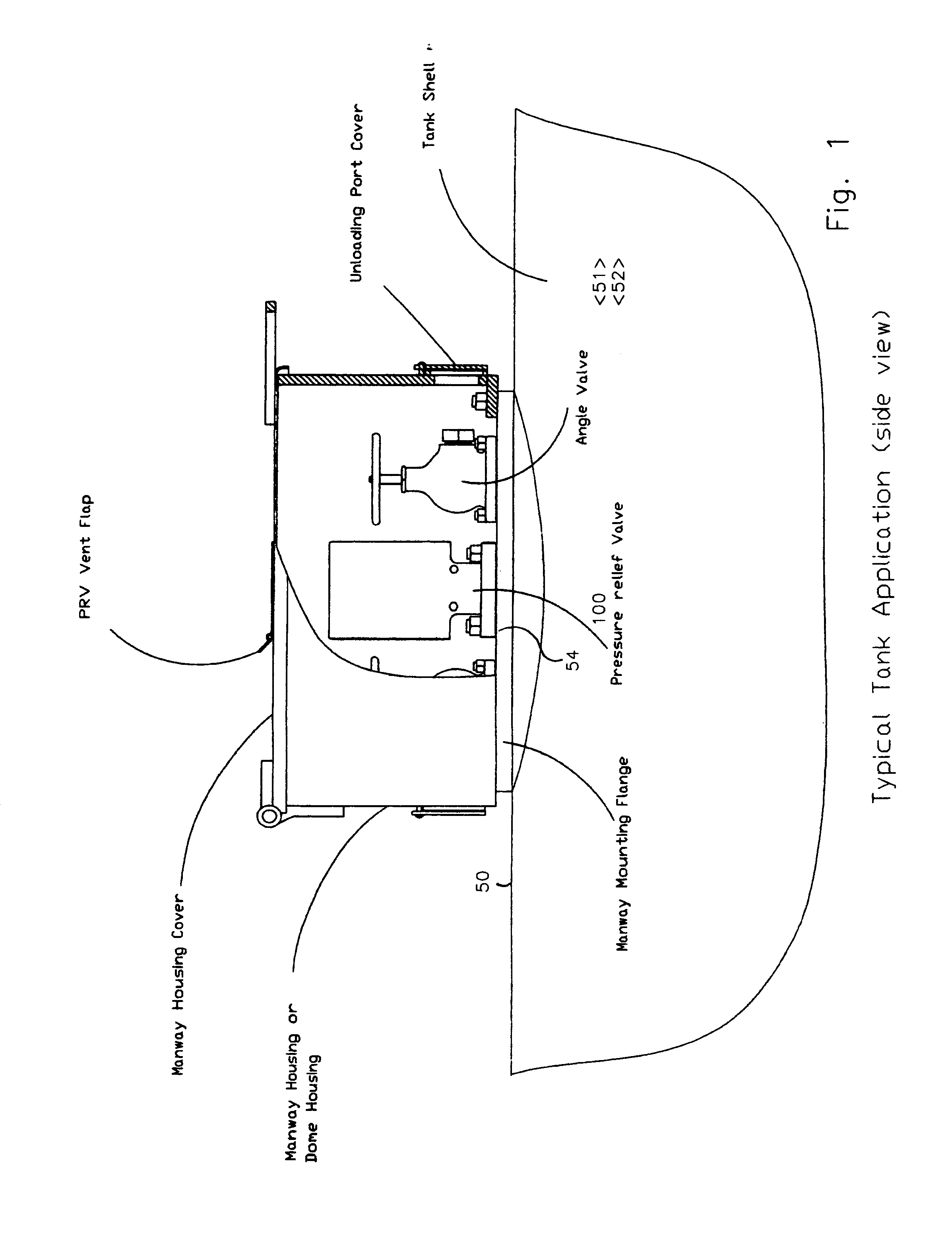
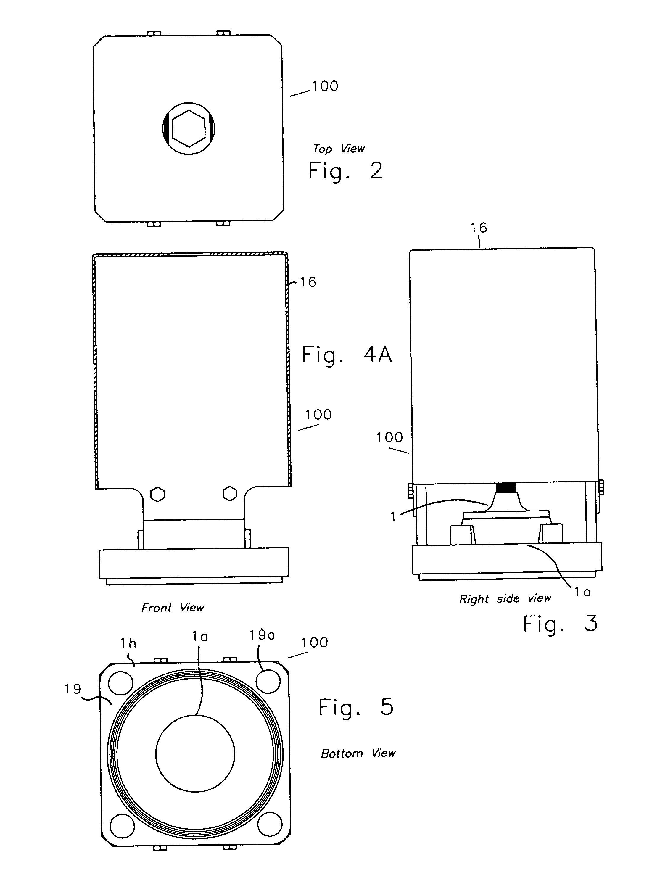
[0073]Referring to FIGS. 1, 2, 4, and 5 in the preferred embodiment pressure relief valve assembly 100 is mounted upon the upper surface 50 of a fluid storage container 51 or rail car transport tank 52. Pressure relief valve assembly 100 includes a preferably circular valve body 1 that circumscribes a single preferably circular valve aperture 1a. Circular valve aperture 1a is continuous with tank car or container opening 54 whenever pressure relief valve 100 is properly attached to tank car or container upper surface 50. Circular valve aperture 1a is preferably positioned within bottom floor 1c of valve body 1 and bottom floor 1c forms valve seat 1d. Valve bottom flange 19 is preferably made of A516 Grade 70 carbon steel or 316L SS stainless steel.

[0074]Referring to FIG. 6, resting upon upper valve body surface 1c and circumscribing circular valve opening 1a is reversibly removable seal retainer disk 4. Seal...


PUM


Abstract

Described herein is an improved externally mounted pressure relief valve that is especially adapted for rail tank cars or other large closed containers that contain or transport fluids, including liquids and gases. The pressure relief valve comprises a plurality of spring assemblies, and each spring assembly contains a pre-determined number of spring leaves. Each spring assembly is coiled upon a corresponding spring drum, and each spring drum is penetrated by a corresponding spring drum bolt. The spring assemblies are preferably aligned in at least two horizontal planes that are parallel to each other and normal to the vertical length of a spring block. The spring block and sealing disk are mounted vertically over the valve seat and within the confines of vertically extending spring brackets.

Description

BACKGROUND OF THE INVENTION[0001]The present invention relates generally to pressure relief valves, and more particularly to a pressure relief valve for venting expanding fluids contained in large closed containers. More particularly the present invention relates to a pressure relief valve for venting expanding fluids contained in trucks and rail way tank cars. Railroad tank cars that transport fluids generally comprise two categories: low pressure (general purpose) tanks and pressure tanks. The present invention most particularly addresses pressure tanks which require pressure relief valves. The primary purpose of the pressure relief valve is to vent fluids within the tank and thereby prevent or delay tank failure from increasing internal pressure. In addition, the pressure relief valve should alert persons to evacuate rapidly in the immediate vicinity of a dangerous pressure increase.[0002]A pressure relief valve for a railroad tank car can be internal or external. With internal p...

Claims


Application Information

Patent Timeline
Patent Type & Authority Patents(United States)
IPC IPC(8): F16K17/04
CPCF16K17/044F16K17/0493F16K27/02F17C2205/0332F17C2205/0379F17C2205/0382F16K17/04F16K24/04F16M13/02
Inventor LACROIX, BARRY
Owner KELSO TEHCNOLOGIES INC
Why Eureka
Try Eureka